 This is part 5 of the NSX Distributed Logical Router (DLR) and Edge Services Gateway (ESG) with OSPF configuration guide, describing the configuration of OSPF and DLR DHCP Relay to an external DHCP Server.
This is a five part series describing the steps to deploy DLR and ESG with OSPF:
- NSX DLR and ESG with OSPF – Part 1 – IP Pools, Host and Logical Network Prep
- NSX DLR and ESG with OSPF – Part 2 – Deploy Controller
- NSX DLR and ESG with OSPF – Part 3 – Deploy Logical Switches & DLR
- NSX DLR and ESG with OSPF – Part 4 – Deploy ESG
- NSX DLR and ESG with OSPF – Part 5 – Configure OSPF
What are we trying to do in this section?
- Configure OSPF Area 0 on the DLR and ESG
- Allow the ESG to publish the Default Route via OSPF
- Configure the DLR as a DHCP Relay for all “Internal” DLR Interfaces
- Configure a Static Route on the External Router for the NSX networks.
- Test DHCP Relay, East-West traffic via the DLR and North-South traffic via the ESG.
A diagram to clarify things:
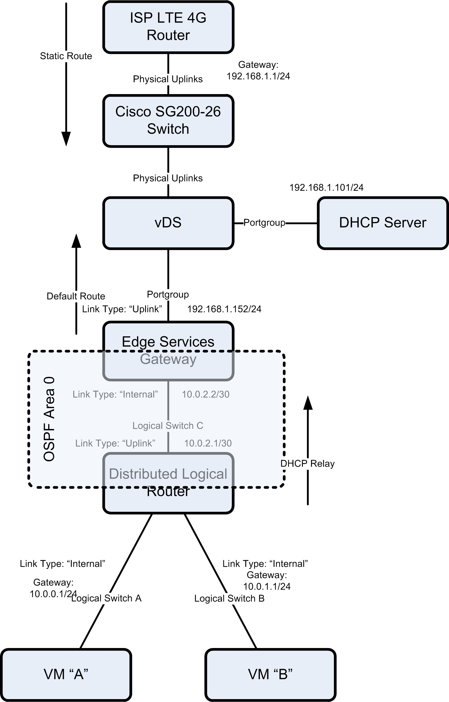
Configure OSPF on the Distributed Logical Router (DLR)
- Login to the vSphere Web Client with an account that has NSX and vCenter Admin privileges.
- Select “Home” and then the “Networking & Security” icon to access “NSX Home”.
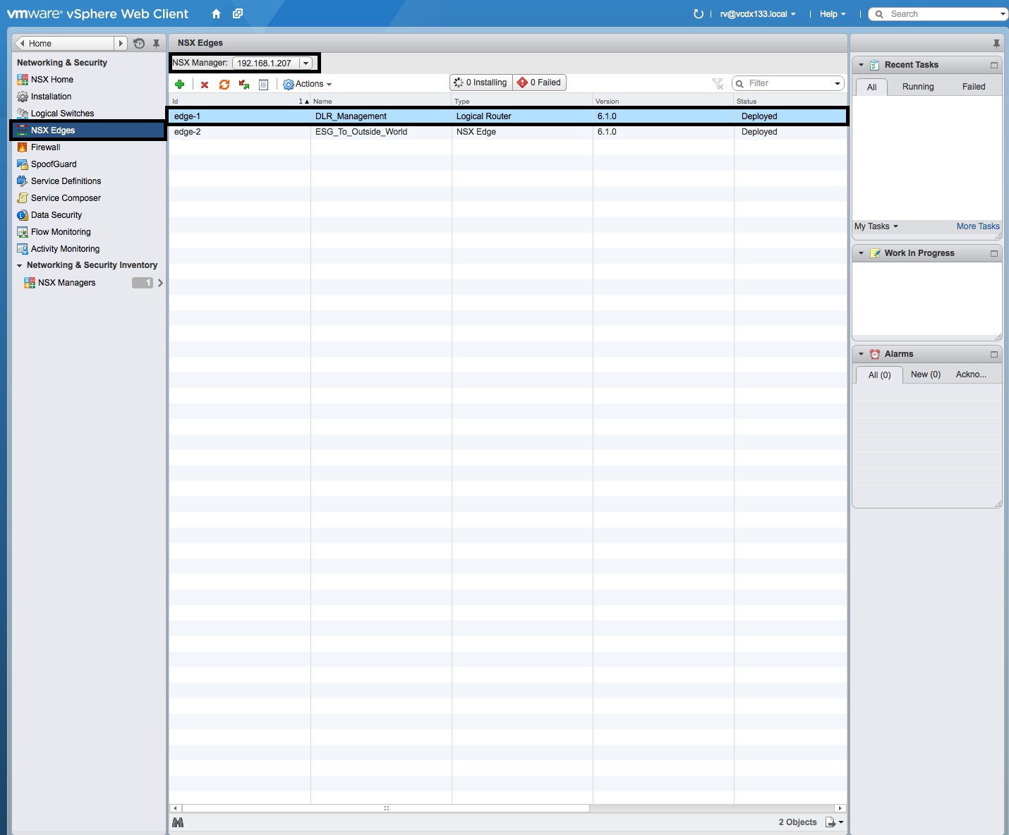
- Select “NSX Edges”, the correct “NSX Manager” IP Address and then double click the “Logical Router” object deployed in Part 3.
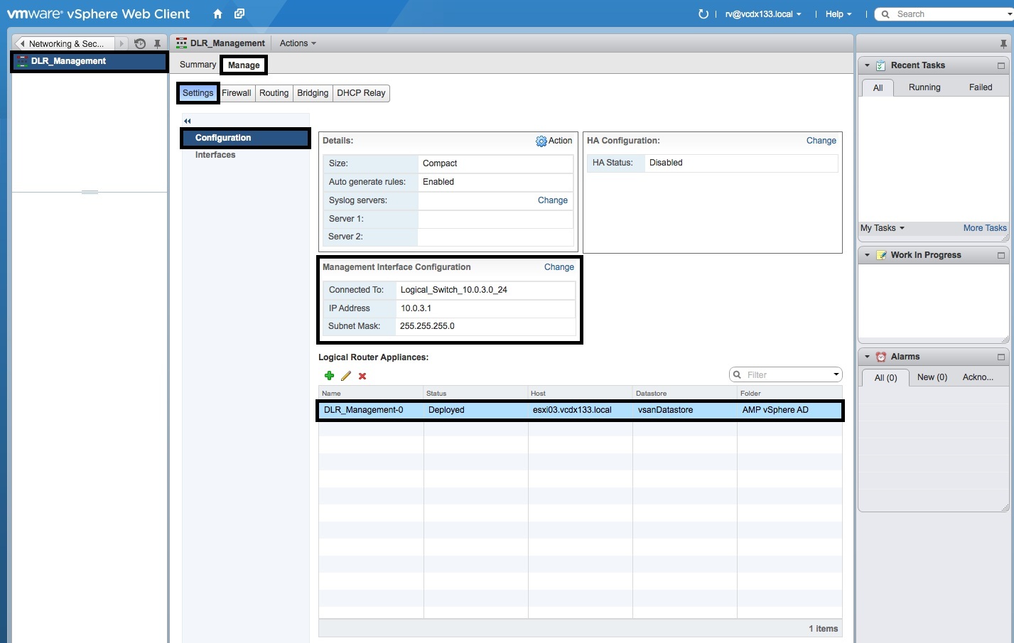
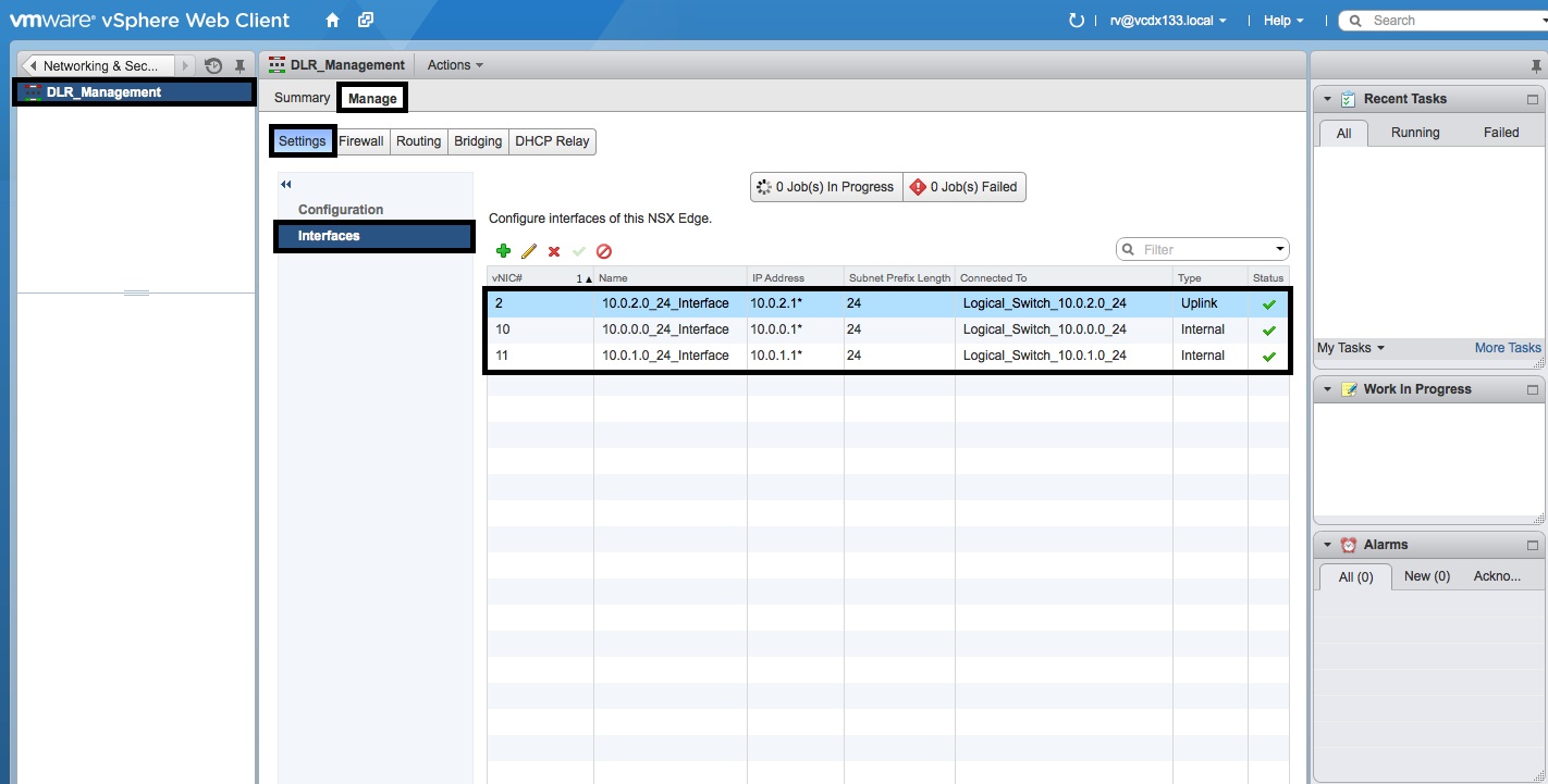
- In the “Logical Router” Management window, select the “Manage” object, the “Settings” tab and then the “Interfaces” object.
- In the “Interfaces” window, verify that a single “Uplink” and two “Internal” interfaces exist.
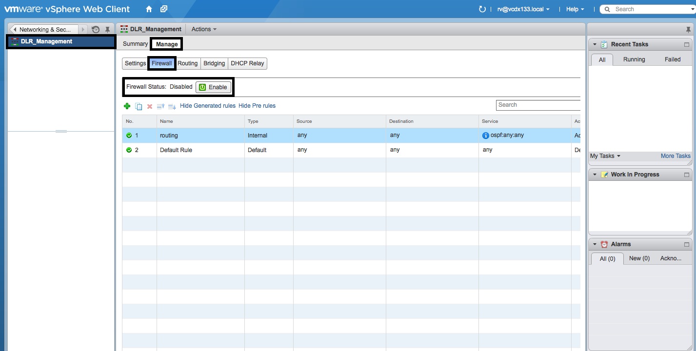
- Select the “Firewall” tab and press the red “Disable” button. The firewall is now disabled.
- Select the “Routing” tab and press the “Global Configuration” object. The press the “Dynamic Routing Configuration” “Edit” button.
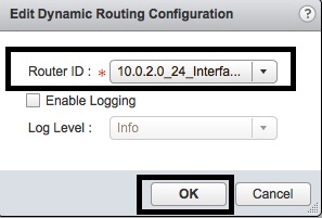
- In the “Edit Dynamic Routing Configuration” window, set the “Router ID” by selecting the configured interface from the drop-down list and then press “OK”.
- In the “Global Configuration” screen, press the “Publish Changes” button.
- Select the “OSPF” object and select the “Not-So-Stubby-Area” (Type NSSA) “Area ID” “51” under “Area Definitions” and press the red “X” to delete it.
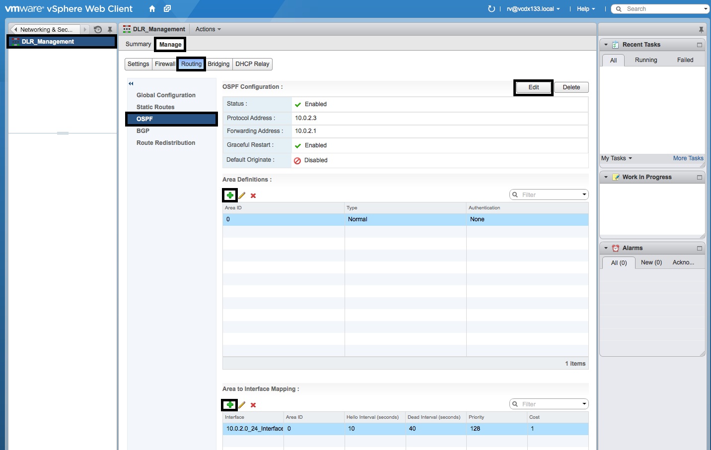
- In the “OSPF” screen, press the green “+” sign under “Area Definitions” to add “Area ID” 0.
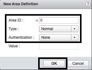
- In the “New Area Definition” window, enter “Area ID” “0”, “Type” “Normal”, “Authentication” “None” and then press the “OK” button.
- In the “OSPF” screen, press the green “+” sign under “Area to Interface Mapping” to add the “Uplink” interface to OSPF “Area ID” 0.
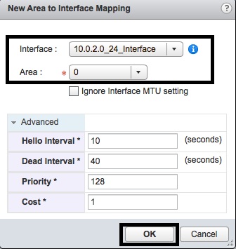
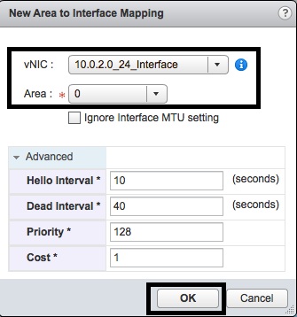
- In the “New Area to Interface Mapping” window, select the “Uplink” interface from the drop-down menu for “Interface”, Area “0” from the drop-down menu for “Area” and then press the “OK” button.
- In the “OSPF” screen, press the “OSPF Configuration” “Edit” button.
- In the “OSPF Configuration” window, tick “Enable OSPF”, enter a free IP Address for the “Protocol Address”, the “Uplink” interface IP Address as the “Forwarding Address” and then press the “OK” button.
- In the “OSPF” screen, press the “Publish Changes” button.


Configure OSPF on the Edge Services Gateway (ESG)
- Login to the vSphere Web Client with an account that has NSX and vCenter Admin privileges.
- Select “Home” and then the “Networking & Security” icon to access “NSX Home”.
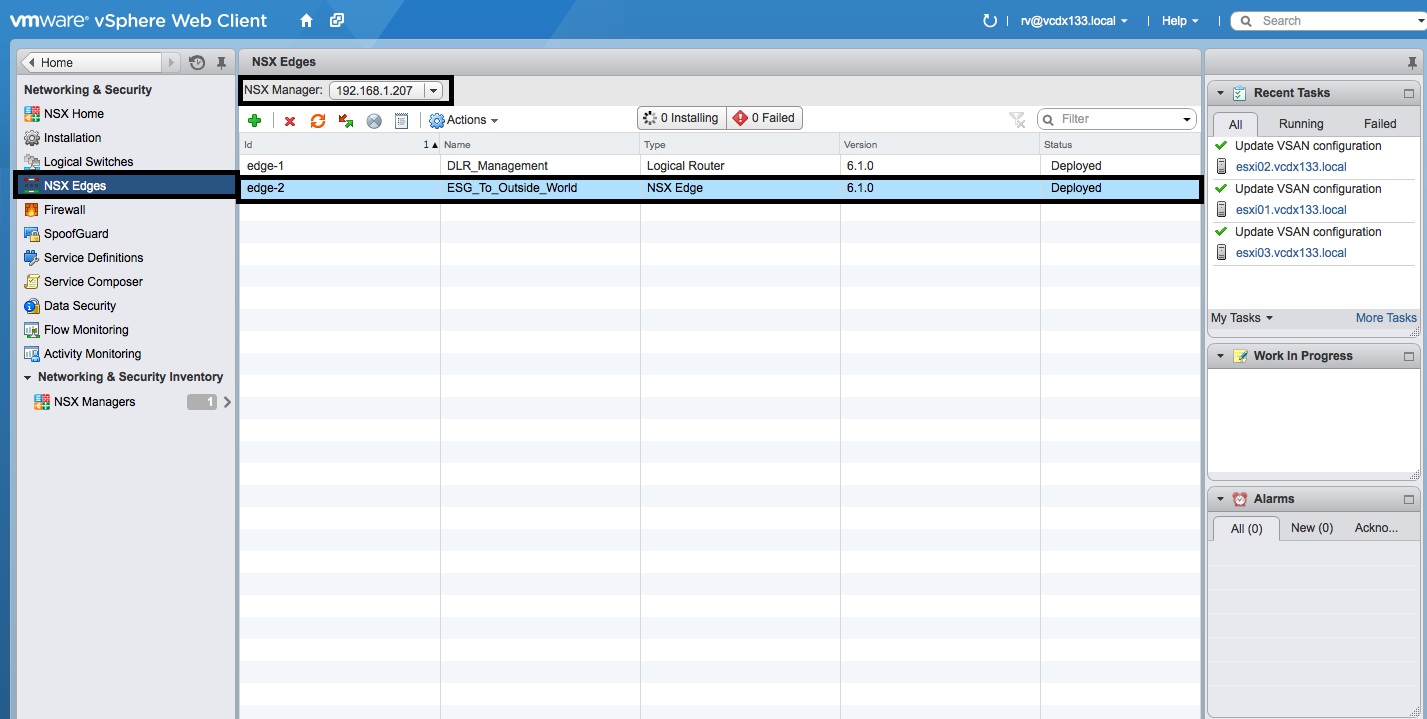
- Select “NSX Edges”, the correct “NSX Manager” IP Address and then double click the “NSX Edge” object deployed in Part 4.
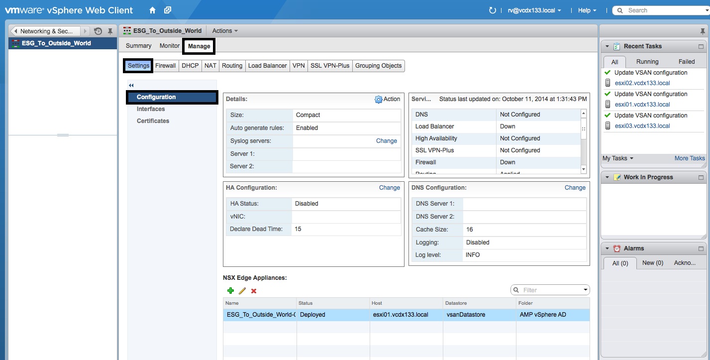
- In the “NSX Edge” Management window, select the “Manage” object, the “Settings” tab and then the “Interfaces” object.
- In the “Interfaces” window, verify that a single “Uplink” and a single “Internal” interface exists.
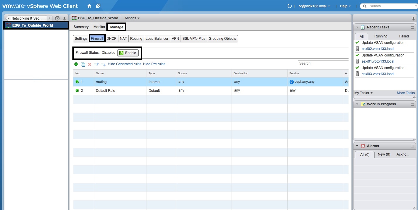
- Select the “Firewall” tab and press the red “Disable” button. The firewall is now disabled.
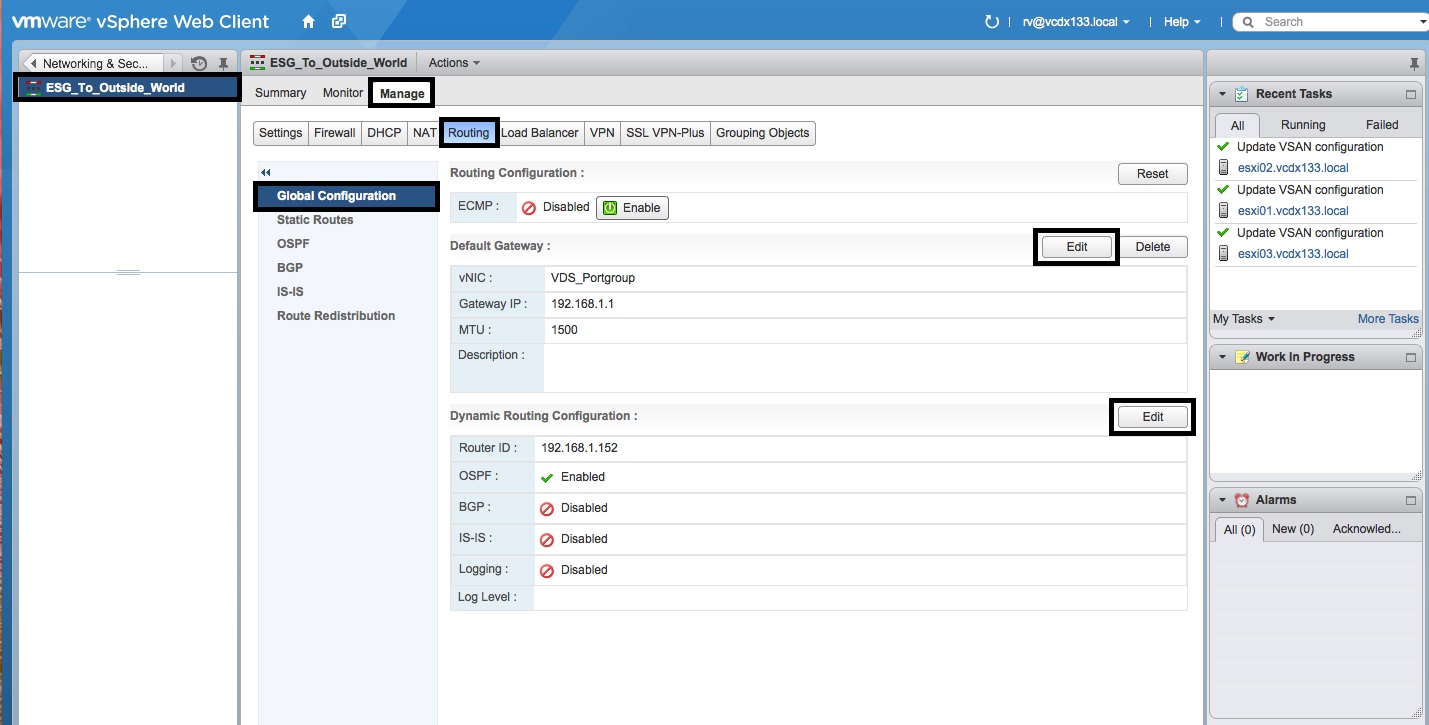
- Select the “Routing” tab and press the “Global Configuration” object. The press the “Dynamic Routing Configuration” “Edit” button.
- In the “Edit Dynamic Routing Configuration” window, set the “Router ID” by selecting the configured interface from the drop-down list and then press “OK”.
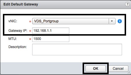
- In the “Global Configuration” window, verify that the “Default Gateway” configured in Part 4 is present.
- In the “Global Configuration” screen, press the “Publish Changes” button.
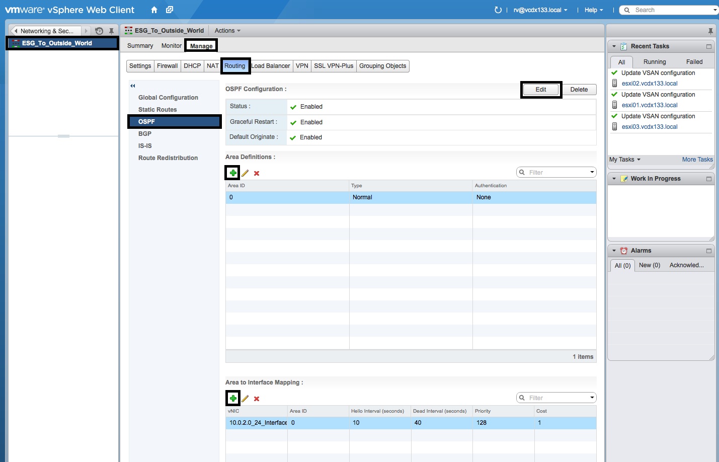
- Select the “OSPF” object and select the “Not-So-Stubby-Area” (Type NSSA) “Area ID” “51” under “Area Definitions” and press the red “X” to delete it.
- In the “OSPF” screen, press the green “+” sign under “Area Definitions” to add “Area ID” 0.
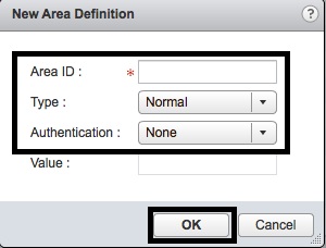
- In the “New Area Definition” window, enter “Area ID” “0”, “Type” “Normal”, “Authentication” “None” and then press the “OK” button.
- In the “OSPF” screen, press the green “+” sign under “Area to Interface Mapping” to add the “Uplink” interface to OSPF “Area ID” 0.
- In the “New Area to Interface Mapping” window, select the “Internal” interface from the drop-down menu for “Interface”, Area “0” from the drop-down menu for “Area” and then press the “OK” button.
- In the “OSPF” screen, press the “OSPF Configuration” “Edit” button.
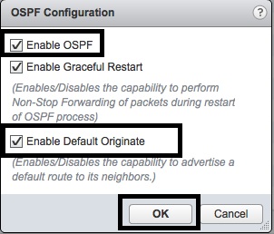
- In the “OSPF Configuration” window, tick “Enable OSPF”, tick “Enable Default Originate” and then press the “OK” button.
- In the “OSPF” screen, press the “Publish Changes” button.


Configure a Static Route on the External Router
The external router or firewall that is terminating the external network requires a “Static” route for the “10.x.x.x/255.0.0.0” networks created within NSX. This is required for return traffic from the external router/firewall to make its way back into the NSX eco-system. The instructions below describe adding a static route to the Huawei LTE 4G Router.
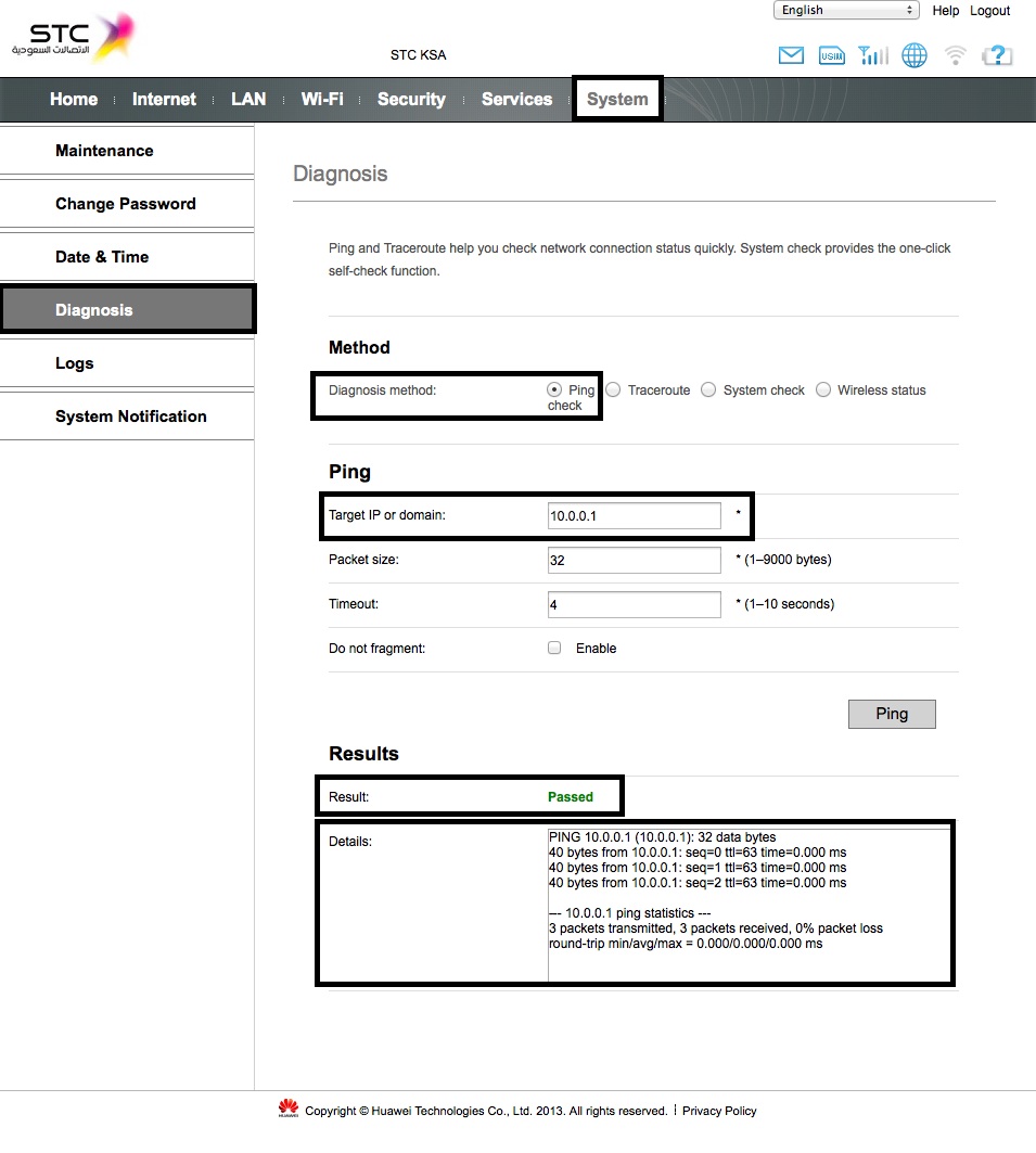
- Login to the Huawei LTE 4G Router management interface with URL: http://<Gateway IP Address> and the default credentials “admin/admin”.
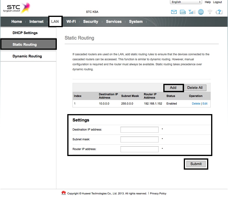
- Select the “LAN” tab and then the “Static Routing” object.
- Then press the “Add” button.
- In the “Add Static Route” window, enter the “Destination IP Address” (eg. “10.0.0.0”), the “Subnet Mask” (eg. “255.0.0.0”), the “Router IP Address” (this is the IP Address from the ESG Uplink Interface) and then press the “Submit” button.
- Verify that the “Static Route” is listed.

Verify OSPF is running End-to-End
- Login to the vSphere Web Client with an account that has NSX and vCenter Admin privileges.
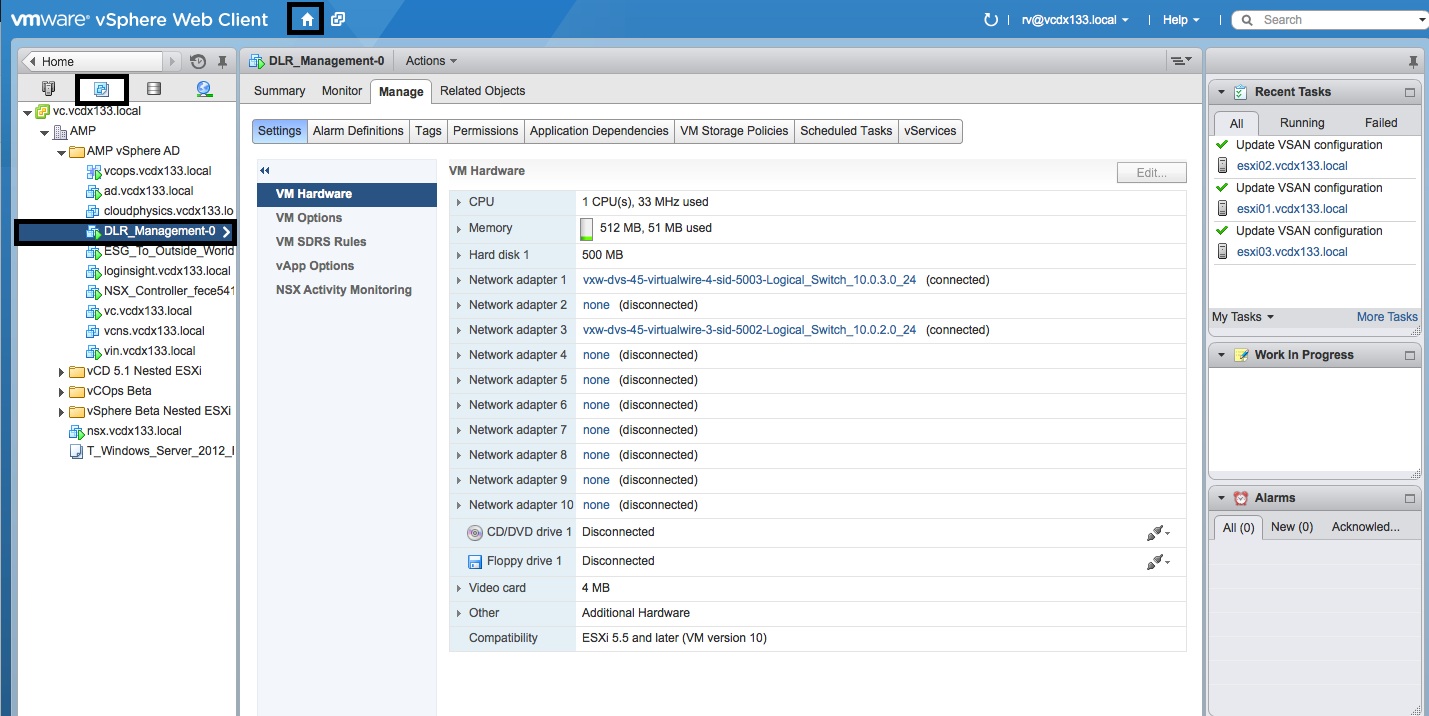
- Select “Home” and then the “VMs and Templates” icon to open the console to the “Distributed Logical Router” created in Part 3.
- Login to the DLR as “admin” with the password specified in Part 3.
- Enter the command “show ip ospf neighbor” and press “Enter”. Verify that the “Neighbor” “State” is “Full/BDR”.
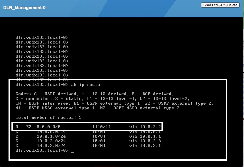
- Enter the command “show ip route” and press “Enter”. Verify that the default route “0.0.0.0” is listed with “O” (OSPF derived) and “E2” (OSPF External Type 2).
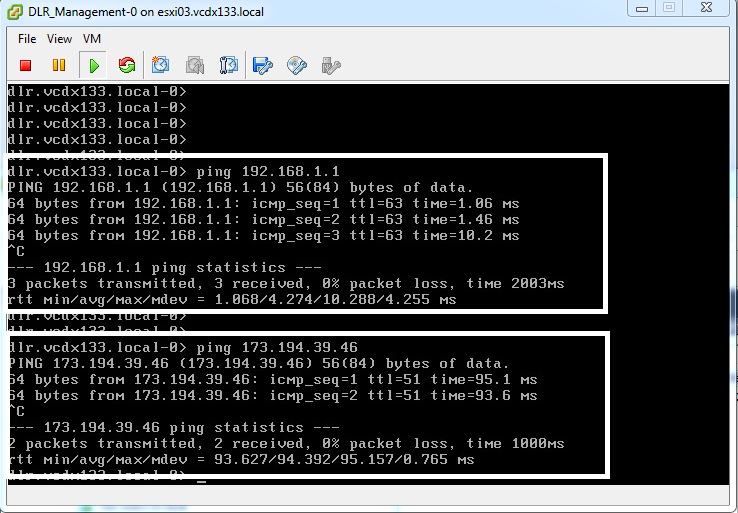
- Before you run the next command, open a Console session via the C# client to the DLR virtual appliance. This is because the ping exit “Control-C” sequence is not recognised from the Web Client.
- Enter the command “ping <external network Gateway IP Address>” and verify that ICMP responses are received. Press “Control-C” to exit ping.
- Enter the command “ping <Google IP Address>” and verify that ICMP responses are received. Press “Control-C” to exit ping. You can find the Google IP Address with the command “nslookup google.com” from “Terminal” (OS X) or “CMD”/”PowerShell” (Windows 7).
- If ping responses are not received for this test, then test ping from the External Network Router/Firewall (eg. ping 10.0.0.1 – LDR Internal Interface Gateway IP)

Configure DHCP Server on the Edge Services Gateway (ESG)
This will only work for an “Internal” interface that is directly connected to ESG virtual appliance. You cannot configure a DHCP Pool on an ESG and then use the DHCP Relay function from the DLR to get an IP address from the ESG.
Configure DHCP Relay on the Distributed Logical Router (DLR)
- Login to the vSphere Web Client with an account that has NSX and vCenter Admin privileges.
- Select “Home” and then the “Networking & Security” icon to access “NSX Home”.
- Select “NSX Edges”, the correct “NSX Manager” IP Address and then double click the “Logical Router” object deployed in Part 3.
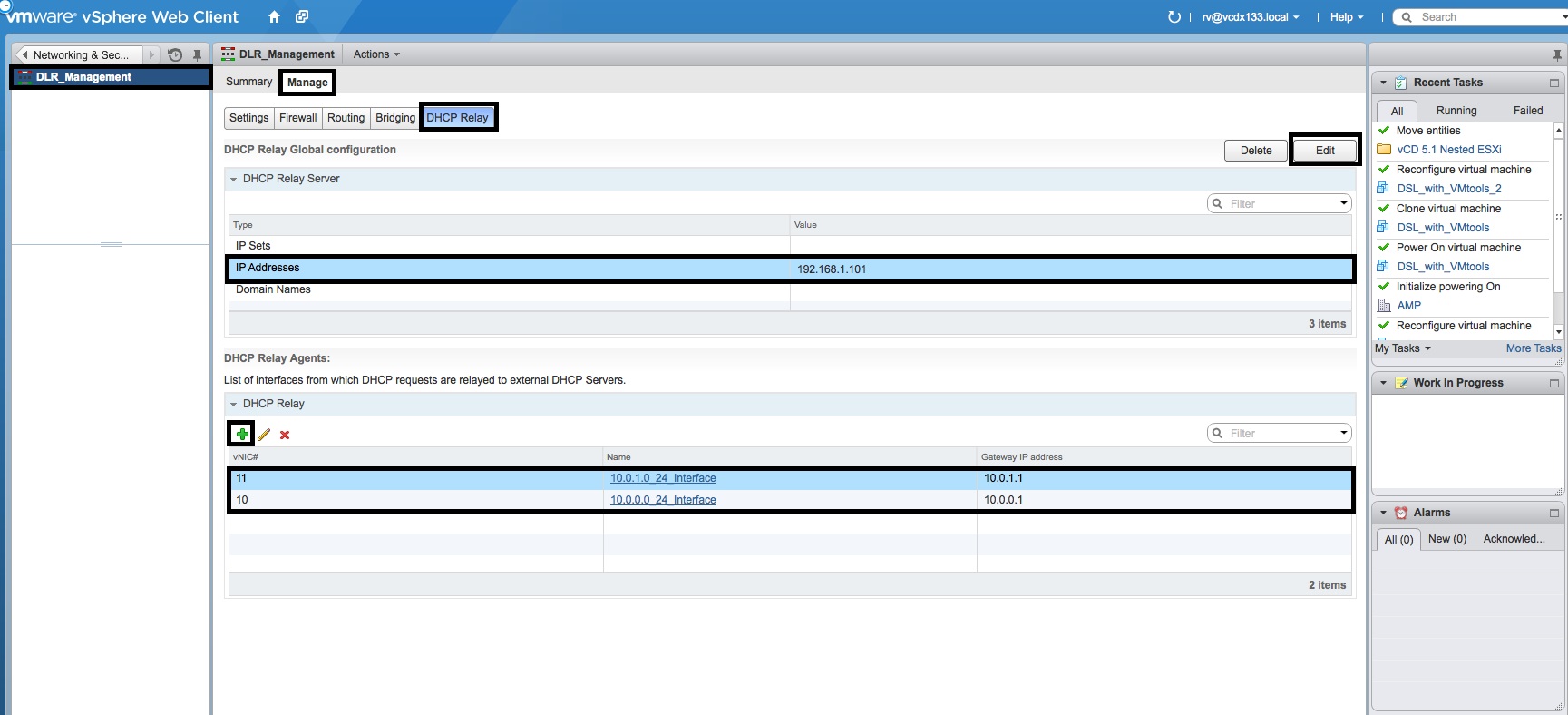
- In the “Logical Router” Management window, select the “Manage” object, the “Settings” tab and then the “DHCP Relay” object.
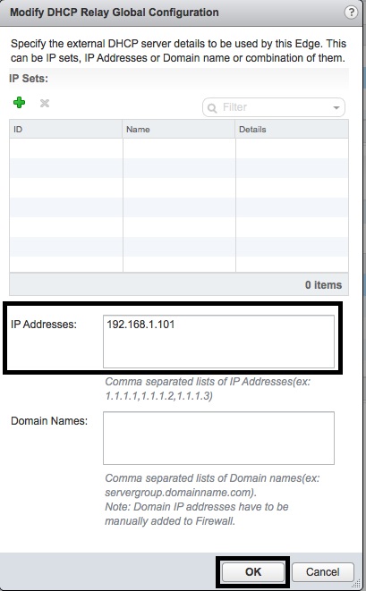
- In the “DHCP Relay” screen, select the “DHCP Relay Global Configuration” “Edit” button.
- In the “Modify DHCP Relay Global Configuration” window, enter the IP Address of the external DHCP server in the “IP Addresses” field and press “OK”.
- In the “DHCP Relay” screen, select the green “+” button under “DHCP Relay Agents”.
- In the “Add DHCP Relay Agent” window, select the “Internal” interface of the DLR from the “vNIC” drop-down list, select the matching “Gateway IP address” from the drop-down list and then press “OK”.
- Do this for each “Internal” interface of the DLR.

Power-On Two VMs and test DHCP Relay, E/W & N/S Traffic
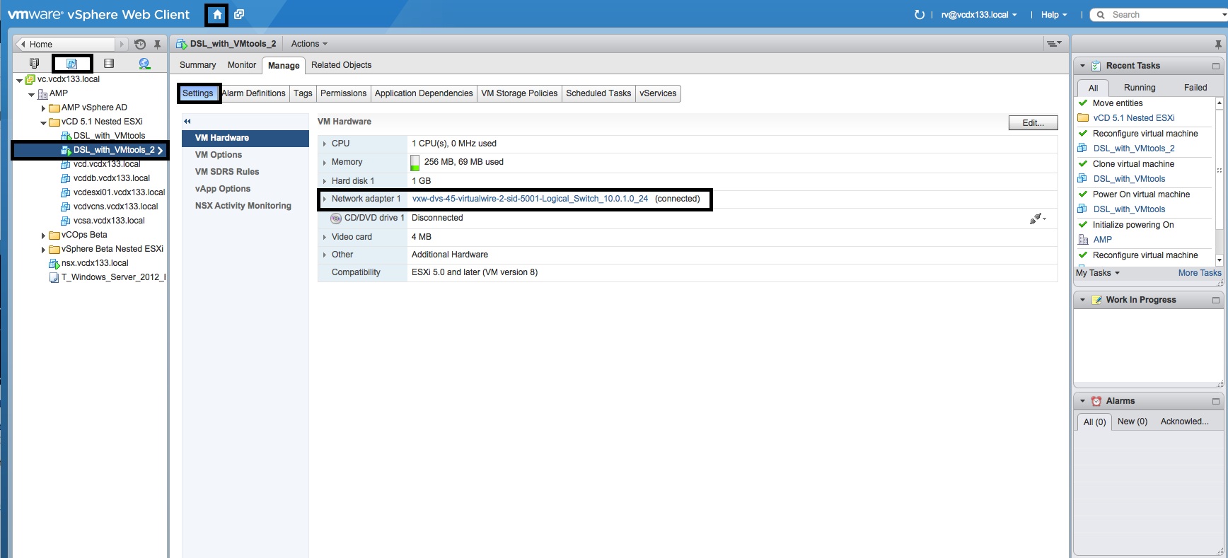
- Assign the vNIC portgroups of the two test VMs to the separate Logical Switches that were defined for the DLR “Internal” interfaces.
- Power-on both VMs and open the consoles for both.
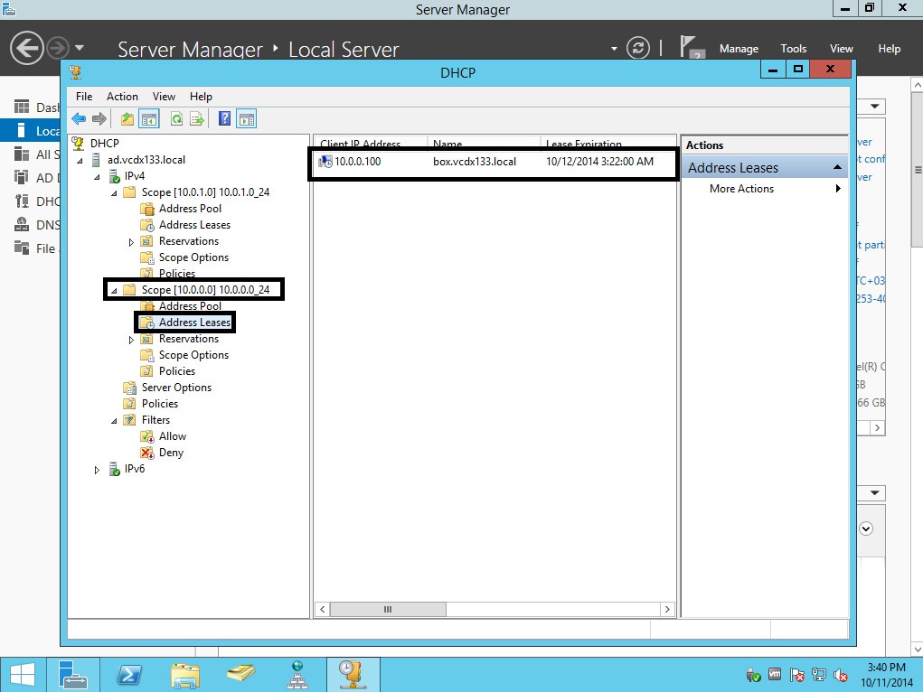
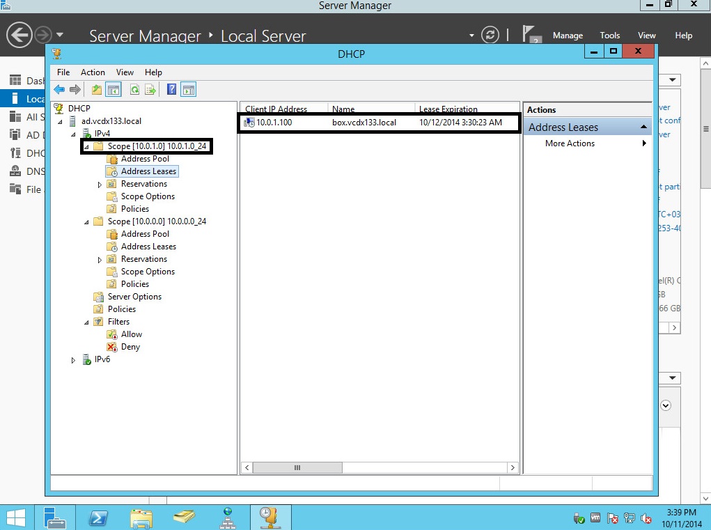
- Access the external DHCP server and verify that “Address Leases” exist for the two Virtual Machines.
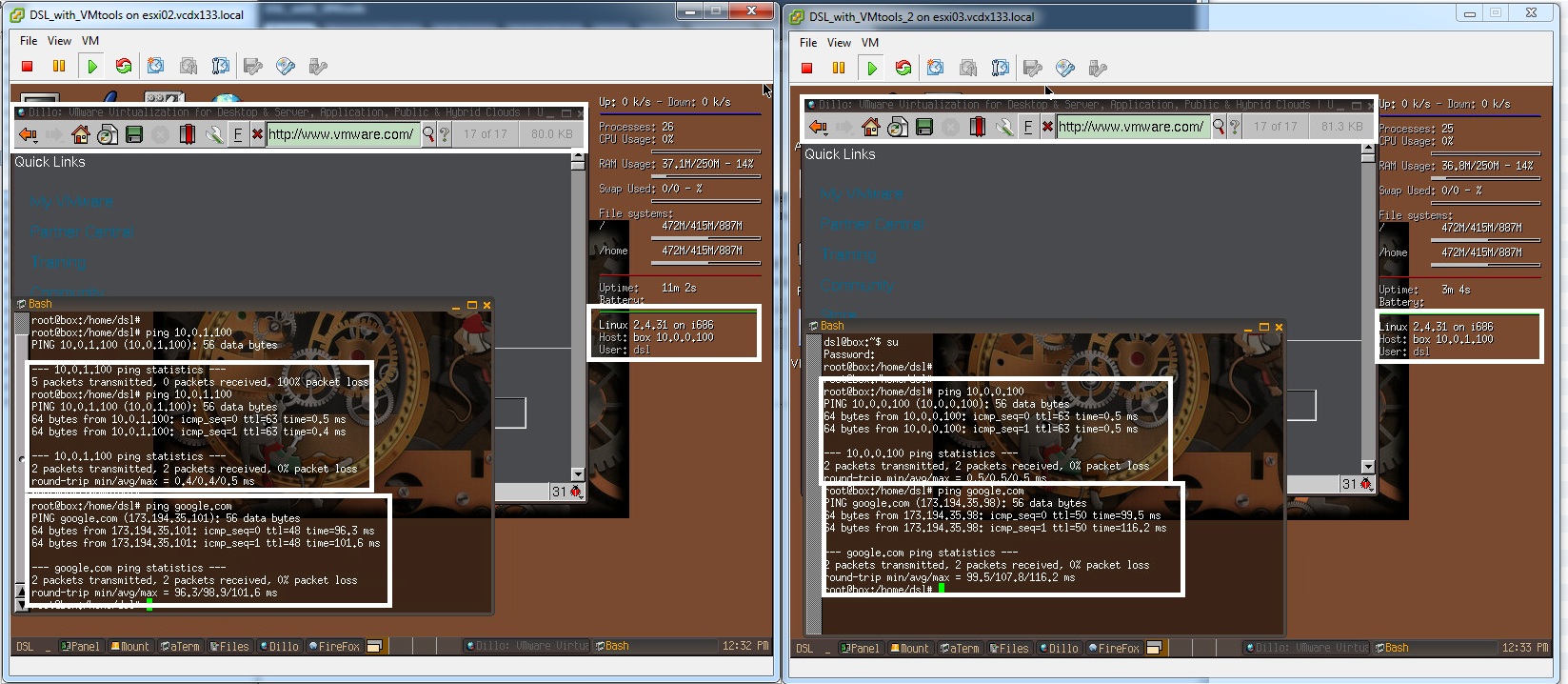
- Verify that IP addresses have been assigned to each VM via DHCP.
- Ping each VM from the other and verify ICMP responses.
- Ping “google.com” from each and verify ICMP responses.
- From the Web browser of each VM, connect to the URL http://www.vmware.com
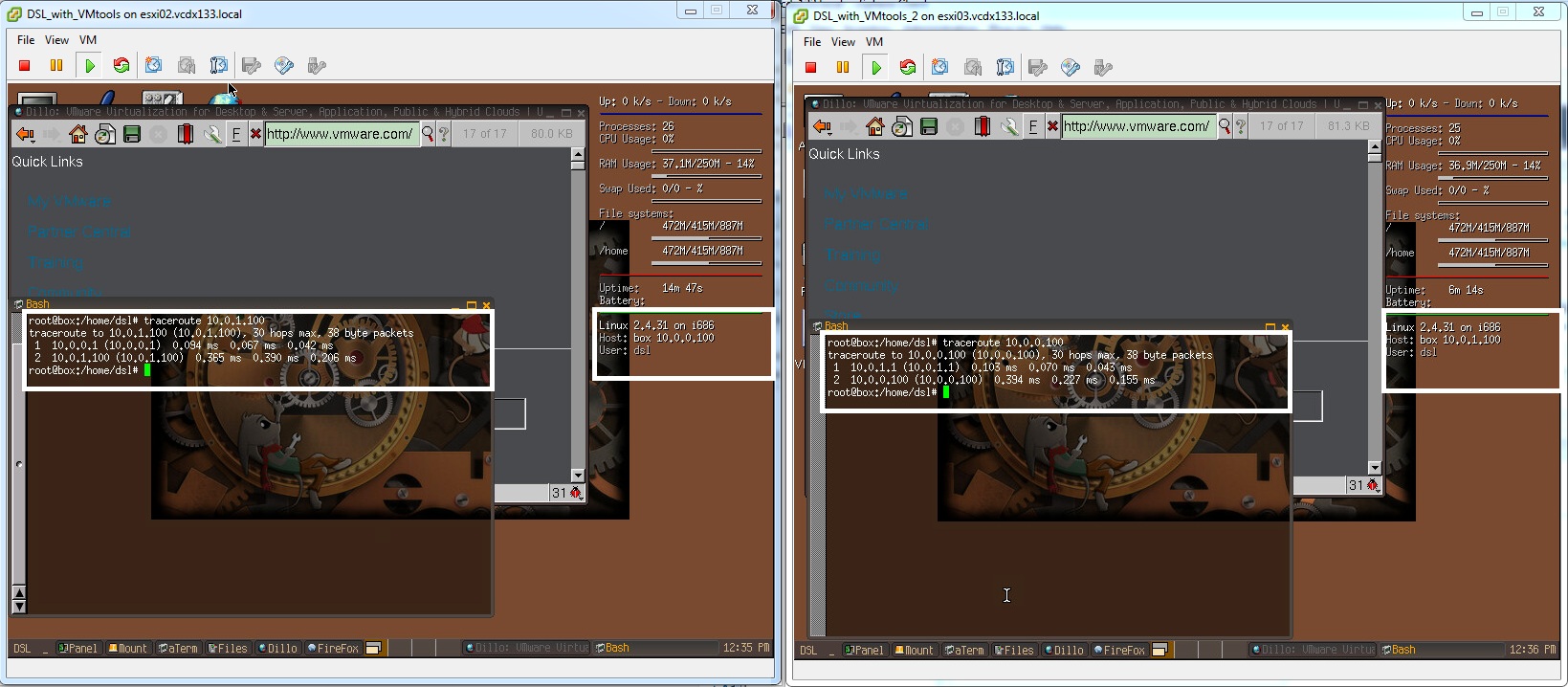
- Traceroute the other Virtual Machine’s IP address using the “traceroute” command and verify two hops are recorded (and vice-versa). Proving that the DLR is routing from VM to VM.
- Configuration and Testing complete!

Other Resources
