 This is a series of posts describing the setup of VMware NSX with the Distributed Logical Router (DLR) connected to an Edge Services Gateway (ESG) configured with OSPF. The DLR has two VMs connected and the ESG has a connection to the Internet. You can build this in the HOL or your home lab.
Update: The term “LDR” has been corrected to “DLR”.
This is a five part series describing the steps to deploy DLR and ESG with OSPF:
- NSX DLR and ESG with OSPF – Part 1 – IP Pools, Host and Logical Network Prep
- NSX DLR and ESG with OSPF – Part 2 – Deploy Controller
- NSX DLR and ESG with OSPF – Part 3 – Deploy Logical Switches & DLR
- NSX DLR and ESG with OSPF – Part 4 – Deploy ESG
- NSX DLR and ESG with OSPF – Part 5 – Configure OSPF
Overview
This configuration is the most simple that you can have, whilst having all of the components of NSX deployed. The idea is to see dynamic routing with logical switches in action for the first time.

This configuration uses the following NSX features:
- Unicast Logical Switches with Unicast Transport Zones
- IP Pools to assign VXLAN Networking and Controller IP Addresses
- Dynamic Routing (OSPF with Area 0 – easiest config) to connect the VM infrastructure to each other and to the outside world
- Distributed Logical Router for connecting two Virtual Machines for East-West traffic
- DLR DHCP Relay for VMs to an external DHCP server
- Edge Services Gateway to connect the LDR to the outside world
NSX features not used (will be explored in later posts – otherwise visit the NSX Link-O-Rama for content from other sources):
- ESG DHCP Services
- Micro-Segmentation
- Bridged Network
- Multicast & Hybrid Transport Zones/Logical Switches
- BGP, IS-IS Dynamic Routing with ECMP option
- Edge Services Gateway features (LB, NAT, Firewall, IPSec, SSL VPN)
- Distributed Firewall, Spoof Guard, Service Definitions, Service Composer, Data Security, Flow Monitoring
The physical lab I am running on is described here.
Prerequisites
- You know what you are doing and have the ability to make changes to vCenter, Active Directory, DNS, etc. (directly or indirectly).
- You have a fully functioning vSphere environment with NSX Manager (as per the NSX Manager – 3 Part series).
- You are building this configuration for a lab environment and are content to use the “minimum” configuration methodology described here.
- Have an External DHCP server that can be use to test DLR DHCP Relay.
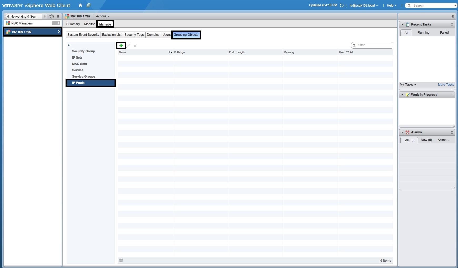
Configure IP Pools
IP Pools are required to build the NSX Controller and VXLAN Networking (part of Host Preparation).
- Login to the vSphere Web Client with an account that has NSX and vCenter Admin privileges.
- Select “Home” and then the “Networking & Security” icon to access “NSX Home”.
- Select “NSX Managers”, the “Manage”, the “Grouping Objects” icon, “IP Pools” and then the green “+” object.
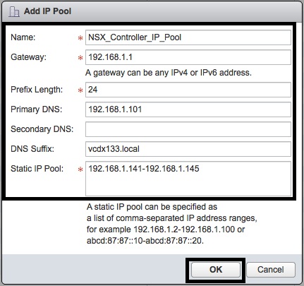
- In the “Add IP Pool” windows, add the “Name”, “Gateway” IP Address, “Prefix Length”, “Primary DNS”, “DNS Suffix” and “Static IP Pool”. Then press “OK”.
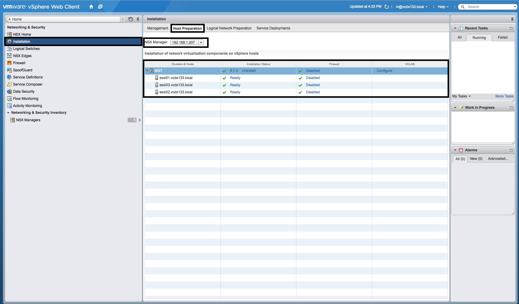
Host Preparation
- Login to the vSphere Web Client with an account that has NSX and vCenter Admin privileges.
- Select “Home” and then the “Networking & Security” icon to access “NSX Home”.
- Select “Installation”, the “Host Preparation” tab and the correct “NSX Manager” IP Address.
- In the “Installation Status” column for the “Cluster”, press the “Install” button and wait for the “Installation Status” to be “Ready” with a green tick.
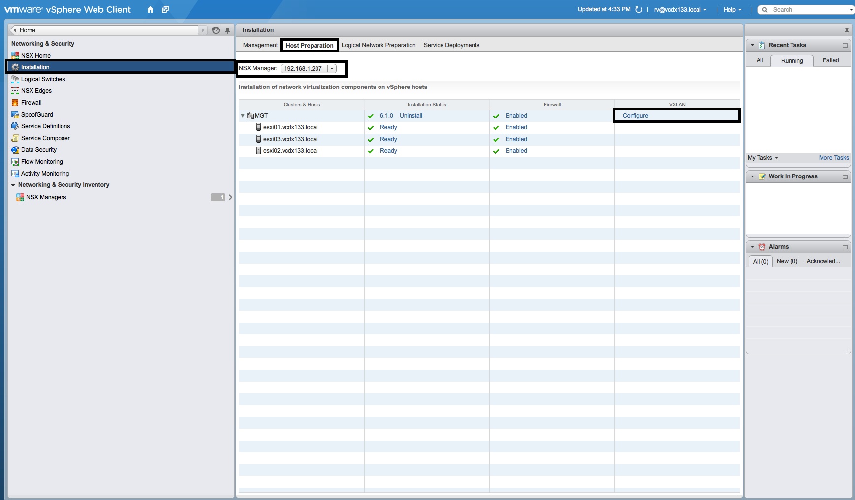
- In the “Firewall” column for the “Cluster”, press the “Disabled” link and select “Enable” from the popup menu. Wait for the “Firewall” state to be “Enabled” for the entire “Cluster”.
- In the “VXLAN” column for the “Cluster” and press the “Configure” link.
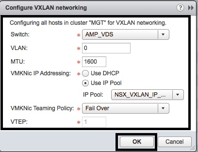
- In the “Configure VXLAN networking” window, set the “Switch”, “VLAN”, “MTU”, “VMKNic IP Addressing” with “IP Pool” and the “VMKNic Teaming Policy” as “Fail Over”. The “VTEP” value remains as “1”. Press the “OK” button.
- In the “VXLAN” column, wait for the “Busy” message to change to “Enabled”.
- The “Host Preparation” tab, should list the “Cluster” with “Installation Status” “6.1.0 Uninstall”, “Firewall” “Enabled” and “VXLAN” “Enabled”.


Logical Network Preparation
- Login to the vSphere Web Client with an account that has NSX and vCenter Admin privileges.
- Select “Home” and then the “Networking & Security” icon to access “NSX Home”.
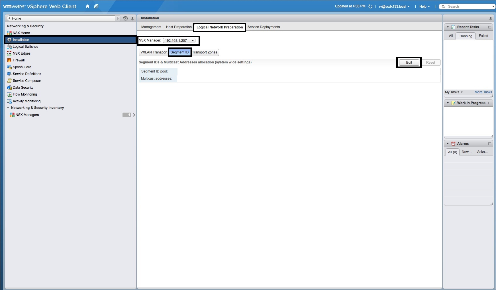
- Select “Installation”, the “Logical Network Preparation” tab and the correct “NSX Manager” IP Address.
- Select “VXLAN Transport” and verify that the “Configuration Status” is “Unconfigure” for the “Cluster” and “Ready” for each “Host”. This was configured in the previous section.
- Select “Segment ID” and press the “Edit” button.
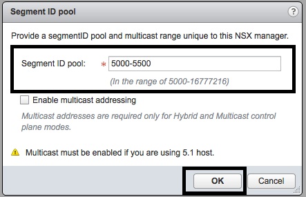
- In the “Segment ID pool” window, enter the “Segment ID pool” of “5000-5500” and press “OK”. Multicast is not required because ESXi 5.5 is being used.
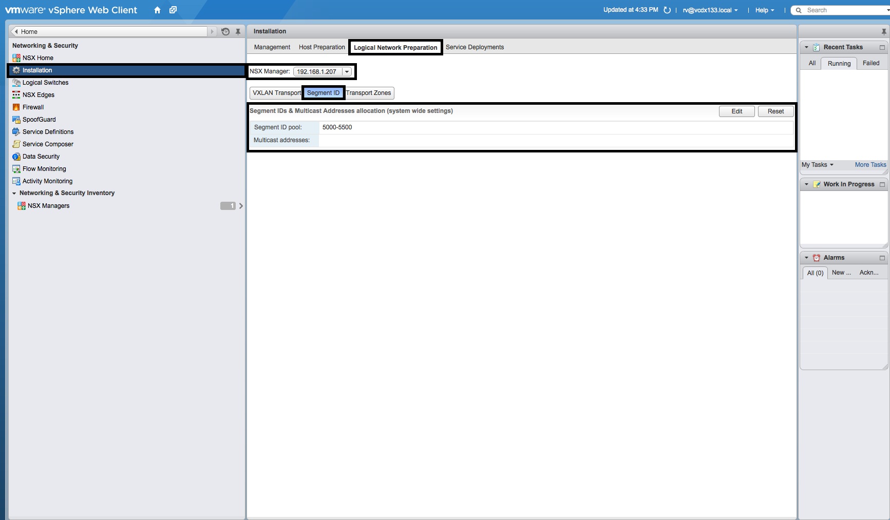
- In the “Segment ID” window, the “Segment ID pool” should be listed.
- Select “Transport Zones” and press the green “+” sign.
- In the “New Transport Zone” window, enter the “Name”, “Description”, “Replication Mode” as “Unicast”, select the “Cluster” and then press “OK”.
- In the “Transport Zones” window, the “Transport Zone” should be listed.
- You are now ready to begin the NSX Controller deployment in Part 2.


Other Resources
