 This is part 3 of the NSX Distributed Logical Router (DLR) and Edge Services Gateway (ESG) with OSPF configuration guide, describing the deployment of the Logical Switches and Distributed Logical Router (DLR).
This is a five part series describing the steps to deploy DLR and ESG with OSPF:
- NSX DLR and ESG with OSPF – Part 1 – IP Pools, Host and Logical Network Prep
- NSX DLR and ESG with OSPF – Part 2 – Deploy Controller
- NSX DLR and ESG with OSPF – Part 3 – Deploy Logical Switches & DLR
- NSX DLR and ESG with OSPF – Part 4 – Deploy ESG
- NSX DLR and ESG with OSPF – Part 5 – Configure OSPF
What are we trying to do in this section?
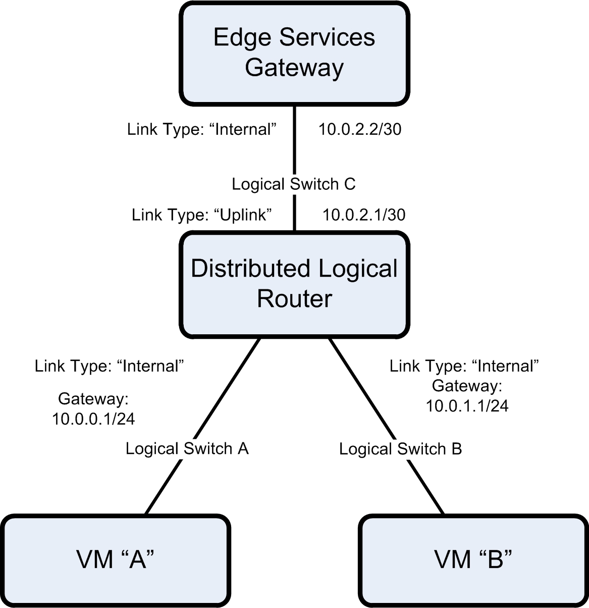
- Configure a Distributed Logical Router (DLR) that will allow Virtual Machines within different networks access to each other and the outside world via the Edge Services Gateway (ESG).
- Configure four Logical Switches that will be used by the VMs, DLR and ESG.
- The DLR will have two “Internal” interfaces, that is used by the Virtual Machine vNICs.
- The DLR will have a single “Uplink” interface, that is connected to the “Internal” interface of the ESG.
- All OSPF routing configuration will be covered in part 5.
A diagram to clarify things:
Deploy the Logical Switches
- Login to the vSphere Web Client with an account that has NSX and vCenter Admin privileges.
- Select “Home” and then the “Networking & Security” icon to access “NSX Home”.
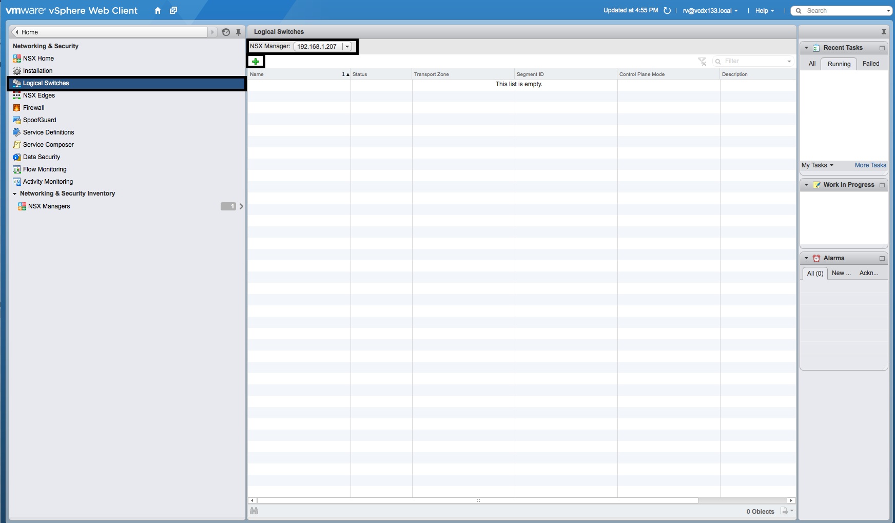
- Select “Logical Switches”, the correct “NSX Manager” IP Address and select the green “+” button.
- In the “New Logical Switch” window, enter the “Name”, “Description”, select the “Transport Zone”, “Replication Mode” as “Unicast” and tick the “Enable IP Discovery” and “Enable MAC Learning” options. Then press the “OK” button.
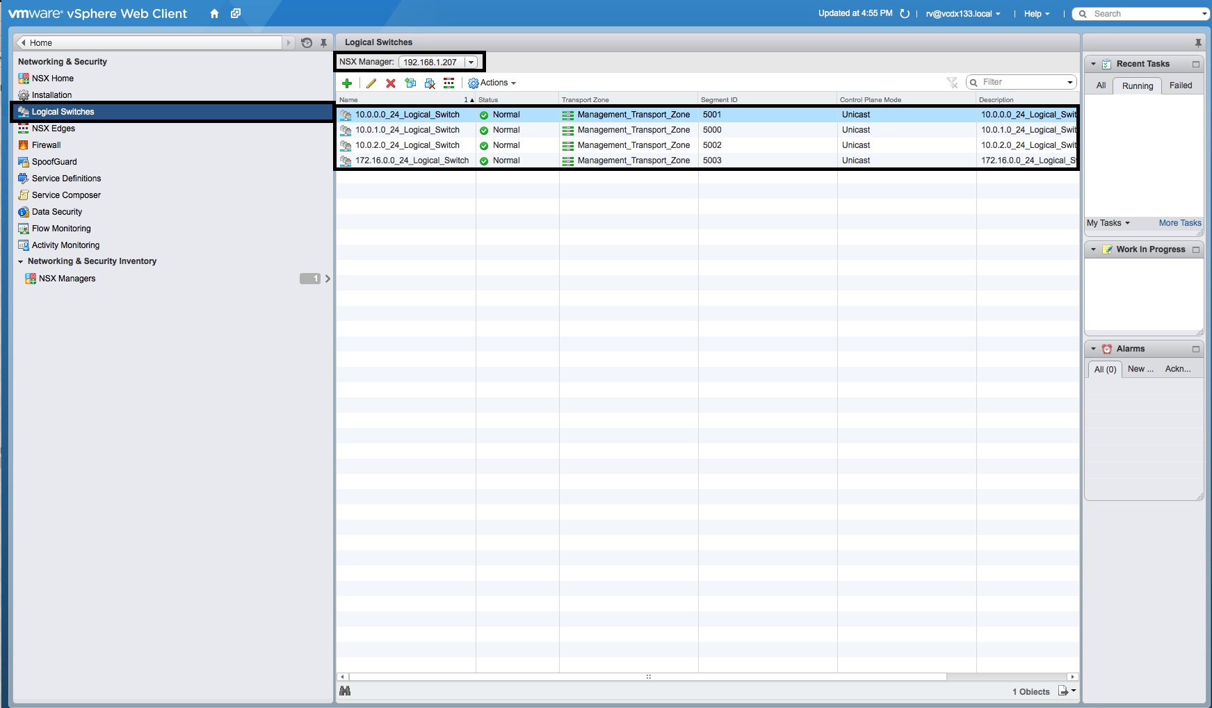
- Repeat this again, so that four Logical Switches appear in the list. Two will be used as “Internal” interfaces for the VMs (to DLR), the third will be the “Uplink” for the DLR to the Edge Services Gateway and the fourth will be the Management interface for the LDR.
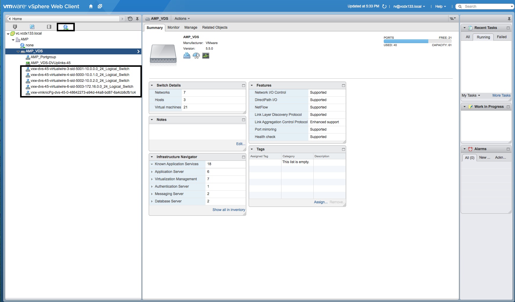
- If you access the “Network” tab from the “Home” screen and view the “Portgroups” of the “Virtual Distributed Switch”, you will notice the additional portgroups that were created by NSX Manager for each Logical Switch.
Note: some of the configuration information in these screenshots does not match the diagram above. The screenshots are provided for context.


Deploy the Distributed Logical Router (DLR)
- Login to the vSphere Web Client with an account that has NSX and vCenter Admin privileges.
- Select “Home” and then the “Networking & Security” icon to access “NSX Home”.
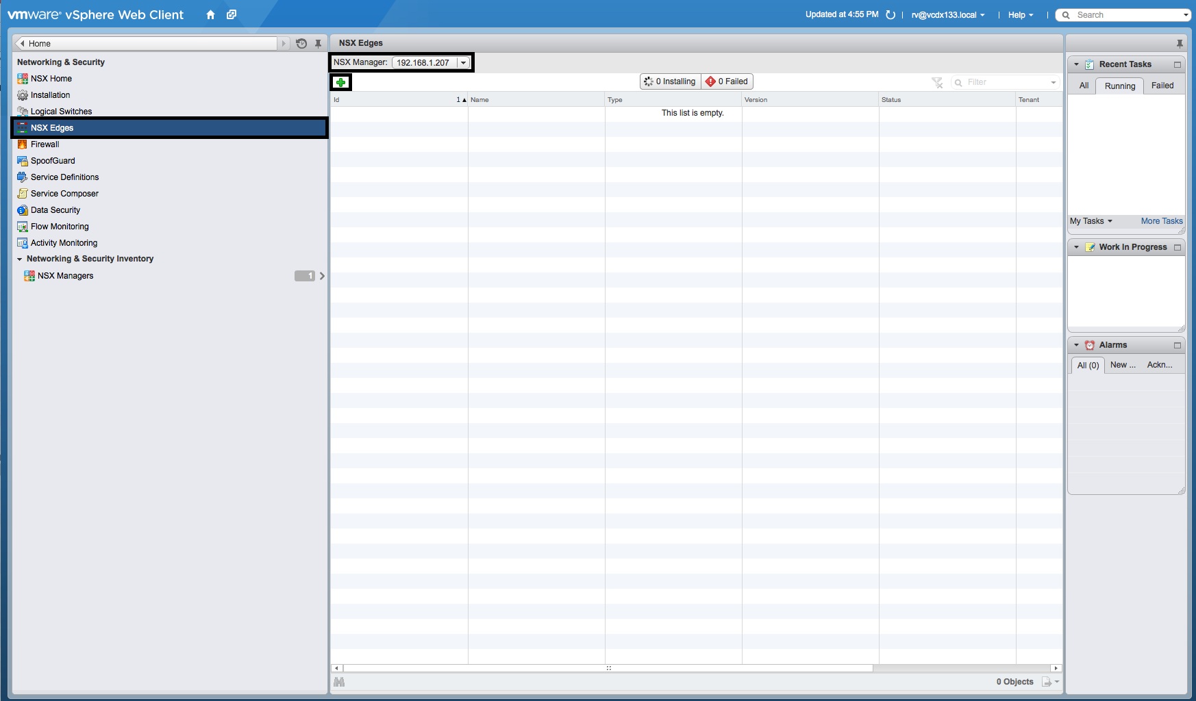
- Select “NSX Edges”, the correct “NSX Manager” IP Address and select the green “+” button.
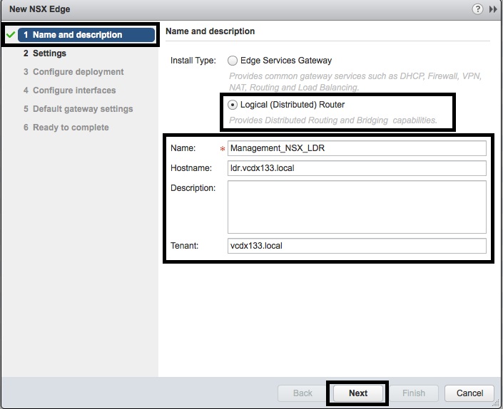
- In the “New NSX Edge” window, select the “Install Type” as “Logical (Distributed) Router” and enter the “Name”, “Hostname”, “Description” and “Tenant”. Then press the “Next” button.
- In the “2 Settings” screen, enter the CLI “admin” Credentials and press “Next”.
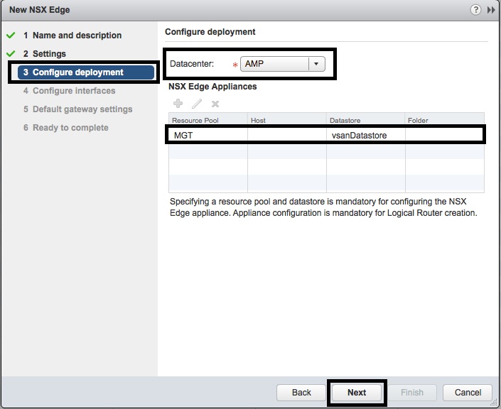
- In the “3 Configure deployment” screen, select the “Datacenter” and press the green “+” button under “NSX Edge Appliances”.
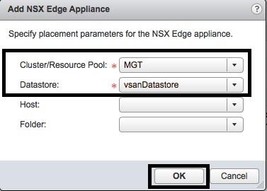
- In the “Add NSX Edge Appliance” window, select the “Cluster/Resource Pool” and the “Datastore” for the DLR. Then press “OK”.
- In the “3 Configure deployment” screen, verify that the “NSX Edge Appliance” is listed and press the “Next” button.
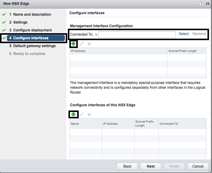
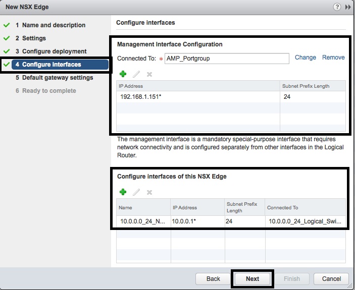
- In the “4 Configure Interfaces” screen, select the “Management Interface Configuration” as the third Logical Switch created earlier and press the green “+” sign.
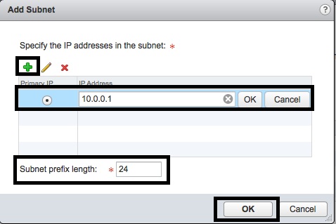
- In the “Add Subnet” window, enter an IP Address from the Logical Switch, enter the “Subnet prefix length” (most likely Class C – “24”) and press “OK”.
- In the “4 Configure Interfaces” screen, press the green “+” sign under “Configure interfaces for this NSX Edge”.
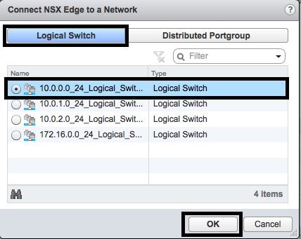
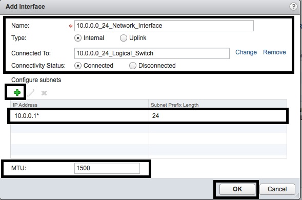
- In the “Add Interface” window, enter the “Name”, select the “Type” as “Internal” for VMs and “Uplink” for ESG and press the “Select” button in “Connected To” to assign the “Logical Switch”.
- In the “Connect NSX Edge to a Network” window, select the “Logical Switch” object and select the “Logical Switch” that will be used for Virtual Machine connectivity.
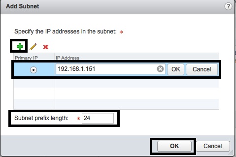
- In the “Add Interface” window, then press the green “+” button under “Configure subnets” to assign an IP Address to the interface.
- In the “Add Subnet” window, pres the green “+” button and enter the Primary IP Address for the interface and set the “Subnet prefix length”. Then press “OK”.
- In the “Add Interface” window, leave the “MTU” at “1500” and press the “OK” button.
- In the “4 Configure Interfaces” screen, add the second interface as an “Uplink”. This will connect to the ESG. Then press “Next”.
- In the “5 Default gateway settings” screen, deselect “Configure Default Gateway” and press “Next”. We will be relying upon the default route to be published via OSPF from the ESG.
- In the “6 Ready to complete” screen, press the “Finish” button.
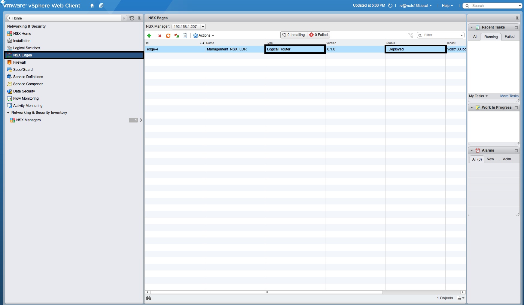
- In the “NSX Edges” window, wait for the “Logical Router” “Status” to change from “Busy” to “Deployed”.
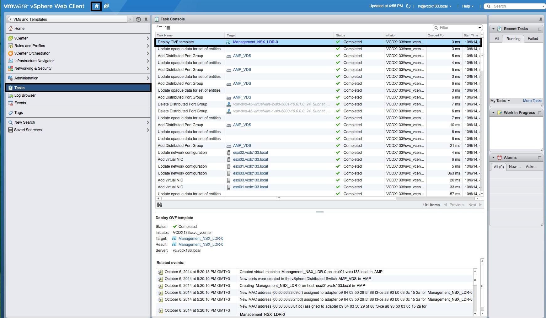
- To view the progress of the “Logical Router” deployment, select the “Task Console” object from the “Home” location.
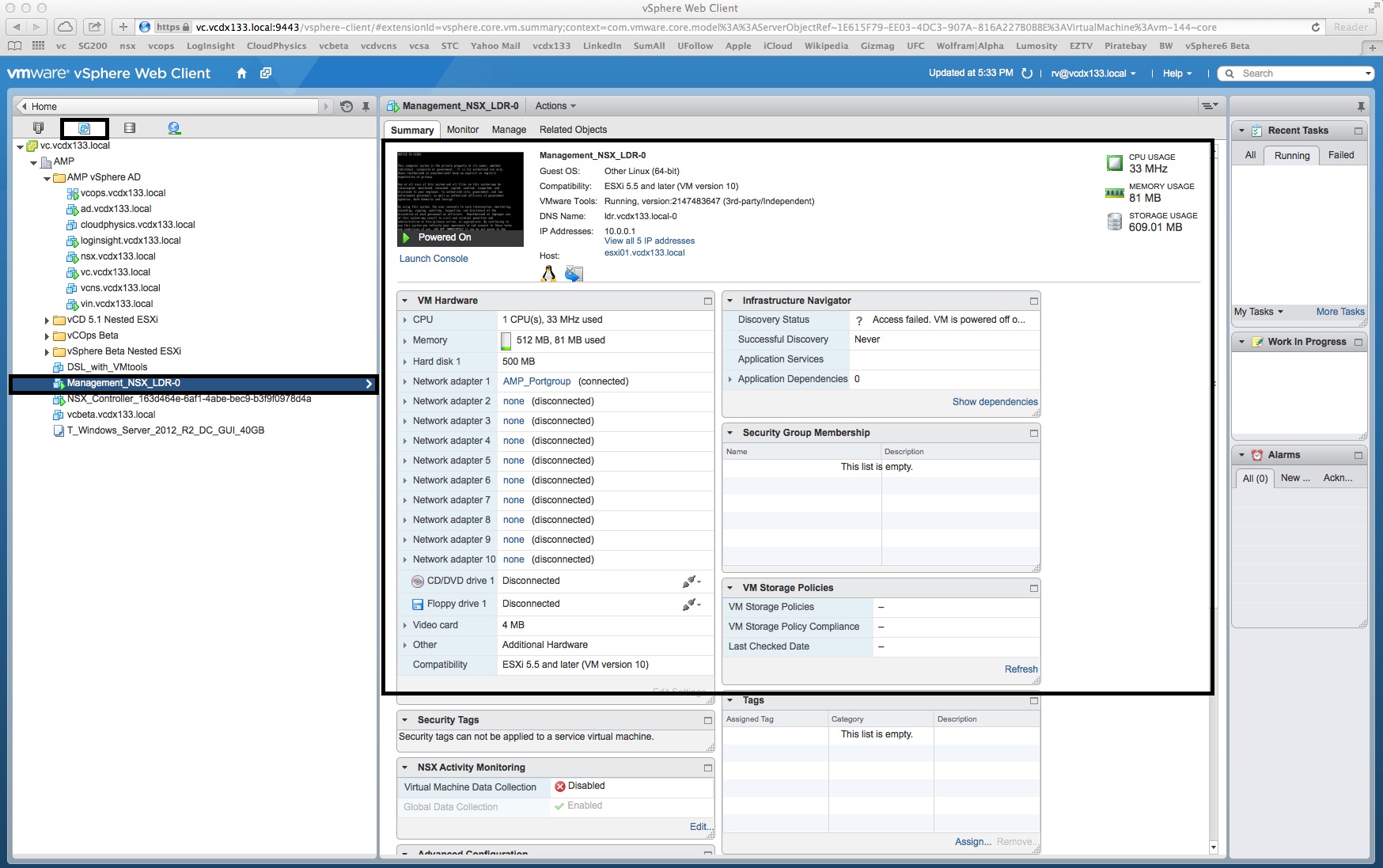
- To view the “Logical Router” virtual appliance within vCenter, select the “VMs and Templates” tab and locate the “<LDR-Name>-0” virtual appliance. You can open the console to login as “admin” once the deployment process has finished.
- From the VM Summary tab, you can see that the LDR is deployed with the default VM Hardware resources of 1 vCPU, 512MB RAM and 500MB Hard Disk. Also note that only a single Console session can exist concurrently and vSphere Infrastructure Navigator has no visibility of the LDR.
- You have completed the “Logical Router” deployment process.
- You are now ready to begin the ESG deployment in Part 4.
Note: some of the configuration information in these screenshots does not match the diagram above. The screenshots are provided for context.


Other Resources
