 This article builds upon the white papers and blogs that are available (listed below) and provides a VCDX-style guide to design decisions that need to be considered for End-to-End Network Quality of Service for vSphere 5.1 with the Cisco Unified Computing System (UCS) and Cisco Nexus switches.
The diagram below provides an overview of the use case.
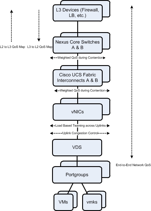
The use case mechanisms are:
- VDS Network I/O Control – Uplink Congestion Control
- VDS LBT – Load Balancing of workloads across Uplinks
- L2 QoS – Weighted QoS across Layer 2 Switch Fabric
- L2/3 to L3/2 QoS Mapping – Translation of DSCP to CoS and vice-versa
- L3 QoS – Weighted QoS within Layer 3 devices
Conceptual Model
- Requirement 1: End-to-End Network QoS
- Requirement 2: Automated Network Congestion control
- Requirement 3: Low Priority Flows will utilise available bandwidth during periods of non-contention
- Requirement 4: Individual workloads will be Load Balanced across Uplinks
- Constraint 1: Cisco UCS Compute System
- Constraint 2: Cisco Nexus Switches
- Constraint 3: Layer 3 Devices that support DSCP
- Assumption 1: At least two vNICs per host
- Assumption 2: Correctly sized, redundant, Enterprise LAN switched network
Logical Design – End-to-End QoS Policy
Design Decision 1: What is the QoS System-wide Policy that you are trying to guarantee?
You need to consider:
- Traffic Directions: East/West, North/South?
- What are the traffic types: Purpose, Latency Sensitive, I/O Intensive, etc.?
- Prioritise the types and map the Priority to CoS (Layer 2) and DSCP (Layer 3)
- MTU Sizes
- Packet drop policies
- Bandwidth limits
- Traffic weight
For Example:

Virtual Switches
Design Decision 2: Number of Virtual Distributed Switches?
Design Decision 3: Number of Uplinks per VDS?
Design Decision 4: Number of Portgroups (with/without VLANs) per VDS?
Design Decision 5: Portgroup Teaming?
Design Decision 6: Network Failover Detection?
Do I break the functional traffic types into separate virtual switches or just use one VDS with two or more uplinks and use Portgroups with VLANs for functional/sub-functional separation? Teaming will be LBT? Network Failover Detection is “Link Status Only”? Then make sure Cisco UCS has the “Action on Uplink Fail Down” policy set. VDS network health check for MTU, VLAN and Teaming should be enabled also.
NOTE: VDS could be replaced with the Cisco Nexus 1000V, however that is outside of the scope of this post. But the same questions are valid.
For Example:

Network I/O Control
Design Decision 7: Share values and Types of System-defined and User-defined Network Resource Pools?
Design Decision 8: Priority tagging with Host Control?
The Network Resource Pool settings will match the Logical End-to-End Network QoS design. If Host Control is configured then ensure that the Cisco UCS “Host Control” policy is set to “Full Control”.
NOTE: With vSphere 5.5, DSCP tagging is supported from the VDS Network Resource Pool to the Host. Therefore, you could implement End-to-End Layer 3 QoS if your Switch fabric is configured with L3 QoS.
Cisco Unified Computing System (UCS)
Design Decision 9: System QoS configuration?
Design Decision 10: Single or Dual VIC adapters per UCS Blade?
Design Decision 11: Number of vNICs per UCS Blade?
Design Decision 12: Rate Limit vNICs?
Design Decision 13: Jumbo Frames?
The System QoS configuration will match the Logical End-to-End Network QoS design. Dual VICs protect against single point of failure; if you have the budget. The number of vNICs per blade will match the VDS design and rate limiting of vNICs should not be used if NIOC is correctly configured. Jumbo frames will match the MTU sizes selected in the Logical design. IMPORTANT: Jumbo frames must be configured consistently across the entire Layer 2 switch fabric.
Multiple VDS with multiple uplinks per VDS can be used to separate traffic types across separate physical switch domains. However, the Cisco UCS must operate in “Switch Mode” and not the default “Host Mode”. Eg. separate DMZ, PCI, HIPAA or Backup switch infrastructure.
For Example:

Cisco Nexus Switches
Design Decision 14: QoS Configuration?
Design Decision 15: vPC?
Design Decision 16: UDLD?
Design Decision 17: Spanning Tree?
Design Decision 18: Jumbo Frames?
The QoS Map settings will match the Logical End-to-End Network QoS design. L2 to L3 map functions and vice versa need to be configured for L3 devices that are not CoS aware. Virtual PortChannel should be used for physical switch redundancy. UDLD should be used on all inter-switch links. Spanning Tree should be configured to protect against switching loops from misconfigured host devices. Jumbo frames will match the MTU sizes selected in the Logical design.
For Example:

Related Resources:

2 thoughts on “End-to-End Network QoS for vSphere 5.1 with Cisco UCS and Nexus”
Comments are closed.