 This is part 2 of the Cisco UCS Configuration Guide. This post is broken into two components: the physical Cisco UCS installation and the initial configuration of the Cisco UCS.
Eight part series, describing how to configure a Cisco UCS from start to finish for a vSphere deployment:
- Cisco UCS Configuration Guide – Part 1 – Overview
- Cisco UCS Configuration Guide – Part 2 – Equipment
- Cisco UCS Configuration Guide – Part 3 – LAN
- Cisco UCS Configuration Guide – Part 4 – SAN
- Cisco UCS Configuration Guide – Part 5 – Server
- Cisco UCS Configuration Guide – Part 6 – Admin
- Cisco UCS Configuration Guide – Part 7 – Firmware Upgrade
- Cisco UCS Configuration Guide – Part 8 – ESXi Driver Upgrade
Physical Installation
Hopefully your Cisco UCS delivery was based upon a configuration where your requirements were collected and a Cisco UCS Engineer designed the system to fit your needs. Normally your Cisco Partner would perform the installation and the entire configuration. However, if that was the case you would not be reading this or maybe you are particular about who works in your Data Center and prefer to do it yourself.
To install the Cisco UCS you need to:
- Locate your rack, it should be empty, clean and in good repair – do not be tempted to mix the Cisco UCS with other hardware infrastructure. YOU WANT A DEDICATED CISCO UCS RACK AND POSSIBLY RESERVE THE RACK NEXT TO IT! This is because the UCS is designed to scale out – you need space for the future.
- Make sure your Data Center Manager understands that the Cisco UCS requires a high inflow of cold air, since it is a high density computing system (Maximum 38,000 BTU/Hr per UCS Chassis).
- The front of the rack is the side that is facing the COLD AISLE. Cold air gets sucked into the front, cooling the hardware and warm air is forced out the back into the HOT AISLE. Do not make the mistake of installing it back to front, otherwise you will have to start again – EASY TO GET IT WRONG!
- Check the power specification of the delivered UCS Chassis and Fabric Interconnects and make sure your Data Center Manager is delivering Power Circuits that match: 2 x 32A circuits per UCS Chassis (2 power cables per 32A connector), 2 x 32A circuits for the PDUs that the Fabric Interconnects connect to. All of my Data Center installs are 220VAC for Australia, Europe and the Middle East, not sure about the US (208VAC or 110VAC?) – CHECK BEFORE YOU BEGIN! DO NOT BE THE GUY WHO FRIED A UCS BECAUSE HE WAS TOO PROUD TO ASK!
- The Cisco UCS has Earth protection bonding points – check with your Data Center Manager if they need to be terminated to the rack earth bonding points and the rack earth bonded to the Data Center Earth mesh. Some companies care about this, others do not.
- Stack the UCS Chassis in the rack first, use the provided rack mounting kit to support the Chassis weight – EACH CHASSIS IS 48KG/107LB IN WEIGHT, USE 4 PEOPLE OR A MECHANICAL AID TO GENTLY POSITION THE EQUIPMENT – the greater the position height, the more difficult it becomes. DROPPING A UCS ON YOUR FOOT IS GOING TO RUIN YOUR WEEK!
- Unpack the Blade Servers and install them in the UCS Chassis. If you have to install additional RAM or VICs, make sure you wear an ESD strap and and connect it to the server frame.
- Once the UCS Chassis are in place, you can now install the Cisco UCS Fabric Interconnects. Make sure you install it facing the correct way. The rear of the Fabric Interconnect (where the hot air comes out) has the slots for the SFPs (10Gb, 1Gb, FC). This provides the shortest cabling path from the Chassis FEX IO Modules to the Fabric Interconnects. If in doubt, attach power and check where the exhaust fans are.
- Existing UCS – If you are unfortunate enough to have an existing UCS on one side of the Data Center with no space in that area and you have to install a new UCS Chassis on the other side, then you will have to use Optical 10Gb CNA cables to make the distance (Non-Standard, Expensive!).
- Existing UCS – Check the port licence count (SSH to the UCS Manager: “scope license”, “show usage”). Make sure you have enough for every port that you intend to configure (Server, Appliance, LAN & SAN).
- WARNING – WHEN YOU START INSTALLING THE CABLING – MAKE SURE YOU DO IT ONE CABLE AT A TIME – OTHERWISE YOU WILL END UP WITH A “SPAGHETTI” RACK (SEE PHOTO BELOW)! EVERYTHING MUST BE NEAT, TIDY & LABELED! OTHERWISE, YOU RISK THE SCORN OF YOUR PEERS.
- Install the PDUs that will provide power to the Fabric Interconnects. Run the cables inside the rack to below the floor tiles or above the rack to the power cable tray (depending on your Data Center standard practices).
- Install the Power Cables from the PDUs to the Fabric Interconnects.
- Install the Power Cables that will provide power to the UCS Chassis.
- Install the 10Gb Ethernet Cables that connect the Fabric Interconnect to the FEX IO Modules of each UCS Chassis. Refer to the diagrams below for recommended layout. Make sure you know how many the design requires (1, 2, 4 or 8).
- FABRIC INTERCONNECT “A” IS ONLY CABLED TO THE LEFT FEX IOM. FABRIC INTERCONNECT “B” IS ONLY CABLED TO THE RIGHT FEX IOM. DO NOT MIX!
- Install the Uplink Cables for LAN and SAN. Make sure you know how many the design requires. Talk to the Network guy and the Storage guy, without them you are going nowhere.
- Install the 1Gb CAT6A cables between the two Fabric Interconnects, this is the cluster heartbeat for UCS Manager High Availability (management only, not data plane).
- Install the 1Gb CAT6A cables that will connect to your Management LAN – these interfaces are where the Management IP addresses will be configured in the next section.
- The RJ-45 Serial Console interfaces can be connected to an out-of-band serial terminal server. Some companies have this as a standard practice, check with your Data Center Manager.
- You are now ready to power on the equipment and move to the initial configuration stage.
Cisco UCS Cabling Plan – Rear:
 Cisco UCS Cabling Plan – Front:

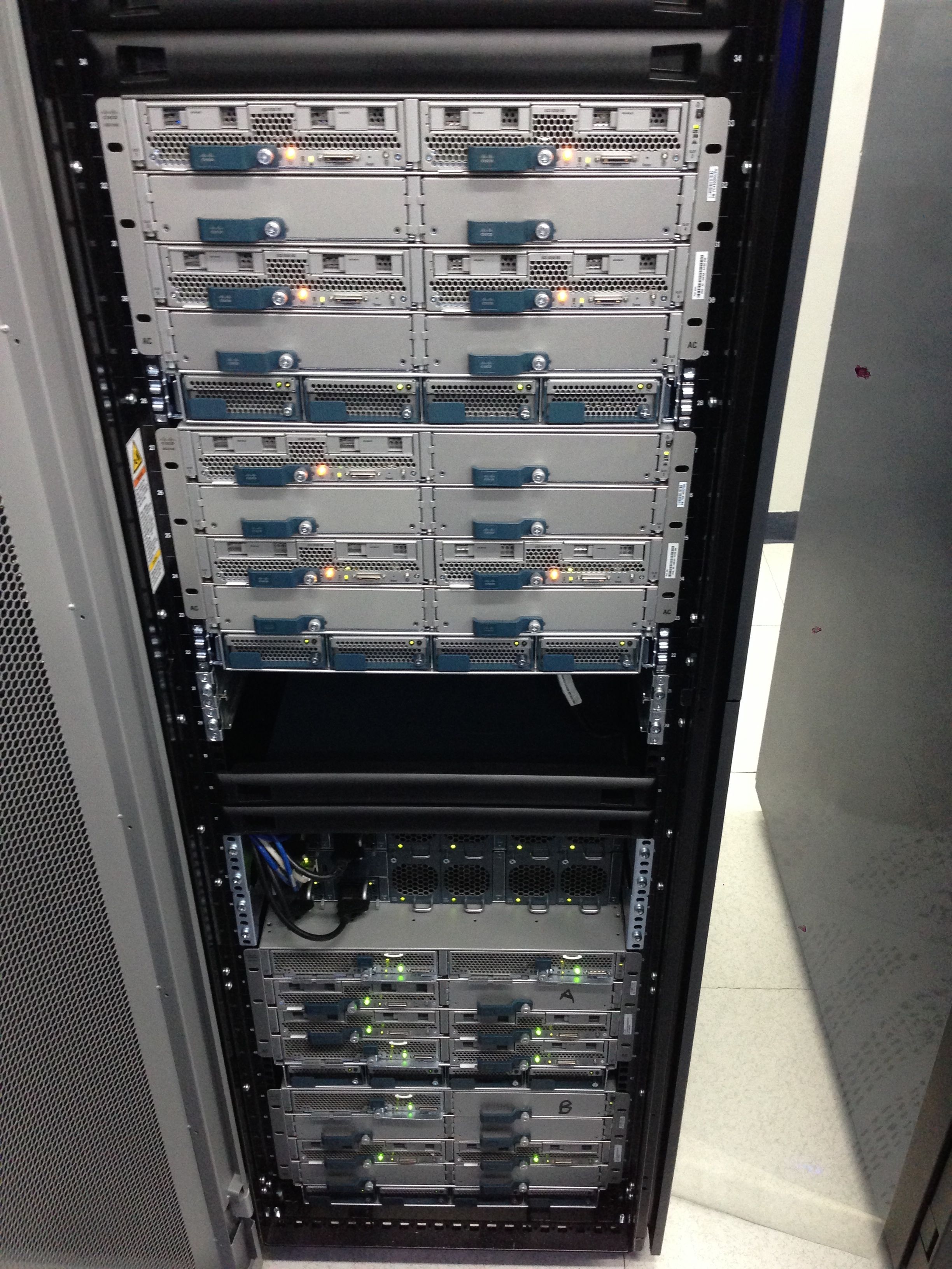
Example Cisco UCS Front View from the COLD AISLE. Note the following:
- Cisco OEM 19″ Server Rack is housing the UCS equipment.
- Plastic blanking panels (black) to restrict cold air leaking to the hot aisle.
- Air gap between racks it blocked by a plastic butcher’s curtain.
- Front of the Fabric Interconnects (cold air in) could be mistaken for the rear (hot air out).
- Front of each UCS Chassis has four power modules that provide power to the blades.
- Front of the UCS Blades have ventilation that allows the fans at the rear to suck cold air in.
- The bottom UCS Chassis are supported by the rack framework (no need to use rack mounting kit).
- The top two UCS Chassis are supported by the supplied rack mounting kit.
- There was no need to bolt the ears of the UCS Chassis into the rack due to the weight of each Chassis with servers (60+KG/133+LB).
 Example Cisco UCS Rear View from the HOT AISLE. Note the following:
- All cabling is firmly bound into position using Velcro ties (supplied with the Cisco OEM rack).
- Optical fiber has a service loop, it is not being stressed.
- All excess cabling is neatly coiled into the cable space of the rack interior (LHS & RHS).
- Rack mounted PDU is used to provide power to the Fabric Interconnects (ordered with the Cisco OEM rack).
- UCS Chassis power cables are connected directly to Data Center UPS circuit breakers (2 cables per 32A connector) – Two on the left connected to UPS-A, Two on the right connected to UPS-B.
- Blue CAT6A cables connect Load Balancer to Fabric Interconnects as “Appliance” Ports.
- Two bottom UCS Chassis are connected to Fabric Interconnect via 8 cables per FEX (High Performance Clusters).
- Two top UCS Chassis are connected to Fabric Interconnects via 4 cables per FEX (VDI, Management Cluster).
- 48 FEX IOM Cables – 4 Uplink cables – Over-subscription ratio of 12:1 (SAN & LAN).

BEWARE – You do not want this “Spaghetti Rack”:

Initial Equipment Configuration
Before you begin, you need the following:
- One system name for the pair of Fabric Interconnects – for this exercise, “UCSFAB”.
- Three IP Addresses in the same subnet, one for each Fabric Interconnect and one for the Cluster virtual IP, complete with subnet mask and gateway IP address – for this exercise, “10.1.1.1/24”, “10.1.1.2/24”, “10.1.1.3/24”, Gateway “10.1.1.254”.
- DNS Server IP and domain name (optional) – for this exercise, “10.1.2.1” and “vcdx133.com”.
- Laptop/PC with serial interface and terminal software (serial 9600 8n1)
- Standard Cisco Serial cable
- PC with Java-enabled browser and access to the management subnet (10.1.1.0/24).
- Turn-off both Fabric Interconnects
To install the Cisco UCS you need to:
- Connect the Laptop to the Console interface of Fabric Interconnect A with the Cisco Serial cable.
- Power-On Fabric Interconnect A.
- Wait for the boot sequence of Fabric Interconnect A to complete, you will know the console connection is OK because boot messages will appear in the terminal software window.
- You are ready to begin when, “Enter the configuration method. (console or gui) ?” appears. Enter “console”.
- “You have chosen to setup a new Fabric interconnect. Continue? (y/n):” appears. Enter “y”. You can use this step to also restore a backup.
- “Enforce strong password? (y/n)” appears. Enter “y”.
- Enter and Confirm the “admin” password.
- “Is this Fabric interconnect part of a cluster (select ‘no’ for standalone)? (yes/no)” appears. Enter “yes”.
- “Enter the switch fabric (A/B)” appears. Enter “A”.
- “Enter the system name:” appears. Enter “UCSFAB”.
- “Physical Switch Mgmt0 IPv4 address:” appears. Enter “10.1.1.2”.
- “Physical Switch Mgmt0 IPv4 netmask:” appears. Enter “255.255.255.0”.
- “IPv4 address of the default gateway:” appears. Enter “10.1.1.254”.
- “Cluster IPv4 address:” appears. Enter “10.1.1.1”.
- “Configure the DNS Server IPv4 address (yes/no):” appears. Enter “yes”.
- “DNS Server IPv4 address:” appears. Enter “10.1.2.1”.
- “Configure the default domain name? (yes/no):” appears. Enter “yes”.
- “Default domain name?:” appears. Enter “vcdx133.com”
- “Following configurations will be applied:” appears with all of the settings from steps 9 to 18.
- “Apply and save the configuration(select ‘no’ if you want to re-enter)? (yes/no):” appears. Enter “yes”. Fabric Interconnect A will then apply the configuration and present a login prompt “UCSFAB-A login:”. Login with the admin account to the prompt “UCSFAB-A#”. Configuration OK.
- Verify that you can ping “10.1.1.2” from a PC that has access to the 10.1.1.0/24 subnet. The cluster IP will not function until after Fabric Interconnect B is added to the management cluster.
- Connect the Laptop to the Console interface of Fabric Interconnect B with the Cisco Serial cable.
- Power-On Fabric Interconnect B.
- Wait for the boot sequence of Fabric Interconnect B to complete, you will know the console connection is OK because boot messages will appear in the terminal software window.
- You are ready to begin when, “Enter the configuration method. (console or gui) ?” appears. Enter “console”.
- “Installer has detected the presence of a peer Fabric interconnect. This Fabric interconnect will be added to the cluster. Continue (y/n)?” appears. Enter “y”. This is detection is through the HA cabling.
- “Enter the admin password for the peer Fabric interconnect:” appears. Enter the admin password set at step 7.
- “Connecting to peer Fabric interconnect… done” appears.
- “Retrieving config from peer Fabric interconnect… done” appears.
- “Physical Switch Mgmt0 IPv4 address:” appears. Enter “10.1.1.3”.
- “Apply and save the configuration(select ‘no’ if you want to re-enter)? (yes/no):” appears. Enter “yes”. Fabric Interconnect B will then apply the configuration and present a login prompt “UCSFAB-B login:”. Login with the admin account to the prompt “UCSFAB-B#”. Configuration OK.
- Disconnect the Laptop and serial cable, you do not need it anymore.
- From your PC (step 21) make sure you can ping “10.1.1.1”, “10.1.1.2” and “10.1.1.3”.
- From this PC open a Java-enabled Browser and enter the URL “http://10.1.1.1” and connect.
- From the Browser click the button “Launch UCS Manager” and accept any Java security warnings. The Java plugin should download and open automatically with a login prompt. Enter the “admin” credentials configured in step 7. You should be presented with the UCS Manager Interface. The system is now ready for policy configuration.
NOTE – Alternate configuration method: GUI with DHCP server. Not covered in this guide.
Example UCS Manager Interface:


One thought on “Cisco UCS Configuration Guide for vSphere – Part 2 – Equipment”
Comments are closed.