 This is Part 3 of the Nutanix XCP Deep-Dive, covering the platform installation into a Data Center.
This will be a multi-part series, describing how to design, install, configure and troubleshoot an advanced Nutanix XCP solution from start to finish for vSphere, AHV and Hyper-V deployments:
- Nutanix XCP Deep-Dive – Part 1 – Overview
- Nutanix XCP Deep-Dive – Part 2 – Hardware Architecture
- Nutanix XCP Deep-Dive – Part 3 – Platform Installation
- Nutanix XCP Deep-Dive – Part 4 – Building a Nutanix SE Toolkit
- Nutanix XCP Deep-Dive – Part 5 – Installing ESXi Manually with Phoenix
- Nutanix XCP Deep-Dive – Part 6 – Installing ESXi with Foundation
- Nutanix XCP Deep-Dive – Part 7 – Installing AHV Manually
- Nutanix XCP Deep-Dive – Part 8 – Installing AHV with Foundation
- Nutanix XCP Deep-Dive – Part 9 – Installing Hyper-V Manually with Phoenix
- Nutanix XCP Deep-Dive – Part 10 – Installing Hyper-V with Foundation
- Nutanix XCP Deep-Dive – Part 11 – Benchmark Performance Testing
- Nutanix XCP Deep-Dive – Part 12 – ESXi Design Considerations
- Nutanix XCP Deep-Dive – Part 13 – AHV Design Considerations
- Nutanix XCP Deep-Dive – Part 14 – Hyper-V Design Considerations
- Nutanix XCP Deep-Dive – Part 15 – Data Center Facility Design Considerations
- Nutanix XCP Deep-Dive – Part 16 – The Risks
- Nutanix XCP Deep-Dive – Part 17 – CVM Autopathing with ESXi
- Nutanix XCP Deep-Dive – Part 18 – more to come as the series evolves (Cloud Connect to AWS and Azure, Prism Central, APIs, Metro, DR, etc.)
Physical Installation
Hopefully your Nutanix XCP delivery was based upon a configuration where your requirements were collected and a Nutanix Solutions Architect designed the system to fit your needs. Normally your Nutanix Partner would perform the installation and the entire configuration. However, if that were the case you would not be reading this or maybe you are particular about who works in your Data Center and prefer to do it yourself.
To install the Nutanix XCP you need to:
- Locate your rack, it should be empty, clean and in good repair – do not be tempted to mix the Nutanix XCP with other hardware infrastructure. YOU WANT A DEDICATED NUTANIX XCP RACK AND POSSIBLY RESERVE THE RACK NEXT TO IT! This is because the Nutanix XCP is designed to scale out – you need space for the future.
- Make sure your Data Center Manager understands that the Nutanix XCP requires a high inflow of cold air, since it is a high density computing system (Maximum 6,483 BTU/Hr per 2RU XCP Chassis – depending upon model).
- The front of the rack is the side that is facing the COLD AISLE. Cold air gets sucked into the front, cooling the hardware and warm air is forced out the back into the HOT AISLE. Do not make the mistake of installing it back to front, otherwise you will have to start again – EASY TO GET IT WRONG!
- Check the power specification of the delivered Nutanix XCP and make sure your Data Center Manager is delivering Power Circuits that match: 2 x 10A circuits per Nutanix XCP Chassis (1 power cable per 10A connector). All of my Data Center installs are 240VAC for Australia, Europe and the Middle East; US will generally use 110VAC – CHECK BEFORE YOU BEGIN! DO NOT BE THE PERSON WHO FRIED AN XCP BECAUSE YOU WERE TOO PROUD TO ASK!
- If not already completed, install the PDUs that will provide power to the XCP Chassis. Run the cables inside the rack to below the floor tiles or above the rack to the power cable tray (depending on your Data Center standard practices).
- The Nutanix XCP Chassis does not appear to have earth protection bonding points – check with your Data Center Manager if the rail kit needs to be terminated to the rack earth bonding points and the rack earth bonded to the Data Center Earth mesh. Some companies care about this, others do not.
- Expanding an existing Nutanix XCP Cluster? Check the interoperability matrix for which models can be mixed.
- If you have multiple Nutanix XCP blocks to install, make sure to rack and stack them together.
- Stack the XCP Chassis from the bottom of the rack first, use the provided rack mounting kit to support the Chassis weight – EACH CHASSIS IS 40KG/90LB IN WEIGHT, USE 2-3 PEOPLE OR A MECHANICAL AID TO GENTLY POSITION THE EQUIPMENT – the greater the position height, the more difficult it becomes. DROPPING AN XCP ON YOUR FOOT IS GOING TO RUIN YOUR WEEK!
- WARNING – WHEN YOU START INSTALLING THE CABLING – MAKE SURE YOU DO IT ONE CABLE AT A TIME – OTHERWISE YOU WILL END UP WITH A “SPAGHETTI” RACK (SEE VERY LAST PHOTO BELOW)! EVERYTHING MUST BE NEAT, TIDY & LABELED! OTHERWISE, YOU RISK THE SCORN OF YOUR PEERS.
- Install the Power Cables from the redundant PDUs to the XCP Chassis.
- You are now ready for LAN connectivity. Make sure you know how many the design requires. Talk to the Network guy, without him you are going nowhere. You will be connecting to redundant Top-of-Rack, End-of-Row Leaf Switches, Access Switches or Collapsed Core Switches.
- Install the 10GbE SFP+ modules in the slots at the rear of the XCP (where the hot air comes out).
- NOTE: The 10GbE SFP+ modules need to be ordered separately with the XCP Chassis. Do not expect them to be included. You need specify the type of Optical or Copper modules (also considering length of integrated cable or fiber patch cord).
- If required, install the 1GbE CAT6A cables that will connect to your Management LAN (assumption).
- Install the 1GbE CAT6A cable that will connect the IPMI to your Management LAN – this interface will have an IP address assigned to it during the install process.
- The KVM (Keyboard – Video – Mouse) interfaces (one per node) can be connected to an out-of-band KVM solution. Some companies have this as a standard practice, check with your Data Center Manager.
- You are now ready to power on the equipment and move to the initial configuration stage.
- Note: As part of the install and setup process, it is recommended to use a flat switch connected to the 1GbE interface for the initial configuration before connecting the cluster to the Data Center network. This will be described in later posts.
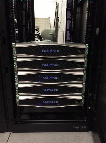
Nutanix XCP Cabling Plan – Rear View

Thank you to Jon Kohler for Installation Example 1 (5 x Nutanix XCP Blocks – 20 nodes).
Note the following:
- Plastic blanking panels (black) to restrict cold air leaking into the hot aisle.
- Assumption: adjacent rack is reserved for Nutanix XCP scale-out
- Each rack has a Top-of-Rack Leaf/Access switch and a Management switch
- All cabling is firmly bound into position using Velcro ties
- Power and Fiber cabling is under floor.
- All excess cabling is neatly tied into the cable space of the rack interior (LHS).
- Nutanix blocks installed from bottom-up.
- Rack mounted PDUs (A and B) are vertically installed on the right hand side of the cabinet.
- XCP Chassis power cables are connected to PDUs A and B.
- 2 x 1GbE and KVM is not connected
- 2 x 10GbE is connected via Copper Cabling to the ToR Switch
- 1 x 10/100MbE IPMI is connected to the management network


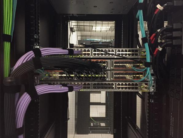
Thank you to Jon Kohler for Installation Example 2 (5 x Nutanix XCP Blocks – 20 nodes).
Note the following:
- No blanking panels to restrict cold air leaking into the hot aisle
- All cabling is firmly bound into position using Velcro ties
- Power and Fiber cabling is under floor
- All excess cabling is neatly tied into the cable space of the rack interior (LHS)
- Nutanix blocks installed from bottom-up
- Rack mounted PDUs (A and B) are vertically installed on the right hand side of the cabinet
- XCP Chassis power cables are connected to PDUs A and B
- Assumption: IPMI (Green CAT6A Cables) connected to separate IPMI Switch (not in photo)
- KVM is not connected
- 2 x 1GbE (Purple CAT6A Cables) connected to redundant End-of-Row Management Switches
- 2 x 10GbE (Black Copper Cables) connected to redundant End-of-Row Cisco Nexus Switches

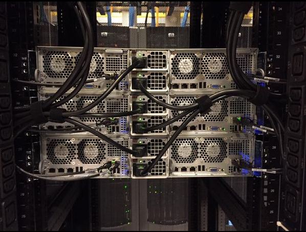
Thank you to Jon Kohler for Installation Example 3 (3 x Nutanix XCP NX-6060 Blocks – 6 nodes).
Note the following:
- No blanking panels to restrict cold air leaking into the hot aisle
- Nutanix blocks installed from top-down
- PDU A is on the right and PDU B is on the left hand side of the cabinet
- All excess cabling is neatly tied into the cable space of the rack interior
- IPMI, 2 x 1GbE and KVM are not connected
- 2 x 10GbE is connected via Copper Cabling to a Switch

BEWARE – You do not want this “Spaghetti Rack”:

Other Resources

Great learning from this series, Thank you Rene.
Hi Rene,
I am new to Nutanix, as I see on photo from Kohler example 1. Why it has total 08 x 10Gbe cable and 04x IPMI cable?
Because it is a four node chassis.